Subaru Outback (BR): Communication System
General Description
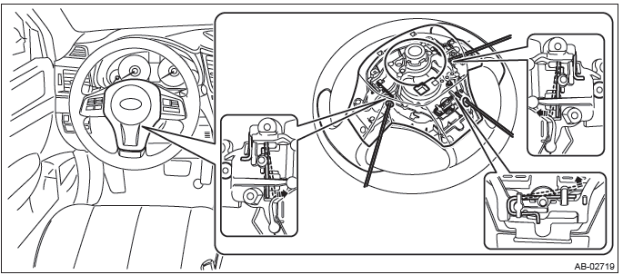
A: COMPONENT
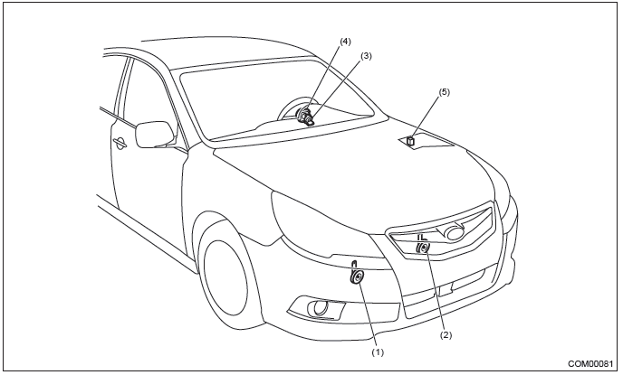
- Hi pitch side horn
- Lo pitch side horn
- Roll connector
- Horn switch (driver's airbag module ASSY)
- Horn relay
B: CAUTION
- Before disassembling or reassembling parts, always disconnect the
battery ground cable from battery.
When replacing the audio, control module and other parts provided with memory functions, record the memory contents before disconnecting the battery ground cable. Otherwise, the memory is cleared.
- Reassemble the parts in the reverse order of disassembly procedure unless otherwise indicated.
- Connect the connectors securely during reassembly.
- After reassembly, make sure that the functional parts operate normally.
- Yellow connectors and harnesses with yellow tapes around them are the connectors and harnesses for the airbag system. Using a tester above such circuits may cause malfunction of airbag system. Follow the cautions for the airbag system in this case. <Ref. to AB-9, CAUTION, General Description.>
- Be careful not to damage the airbag system wiring harness when servicing electrical parts and switches.
C: PREPARATION TOOL
1. GENERAL TOOL

Relay and Fuse
A: LOCATION
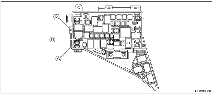

NOTE: For other related fuses, refer to the wiring diagram. <Ref. to WI-15, Power Supply Circuit.>
B: INSPECTION
1. CHECK FUSE.
1) Remove the fuse and check visually.
2) If the fuse is blown out, replace the fuse.
2. CHECK RELAY
1) Check the resistance between relay terminals.
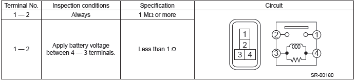
2) Replace the relay if the inspection result is not within the standard value.
Horn System
A: WIRING DIAGRAM
Refer to "Horn System" in the wiring diagram. <Ref. to WI-175, WIRING DIAGRAM, Horn System.>
B: INSPECTION
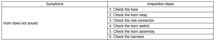
C: NOTE
For operation procedures of each component of the horn system, refer to the respective section.
- Horn ASSY: <Ref. to COM-5, Horn.>
- Horn switch: <Ref. to COM-11, Horn Switch.>
Horn
A: REMOVAL
1) Disconnect the ground cable from battery.
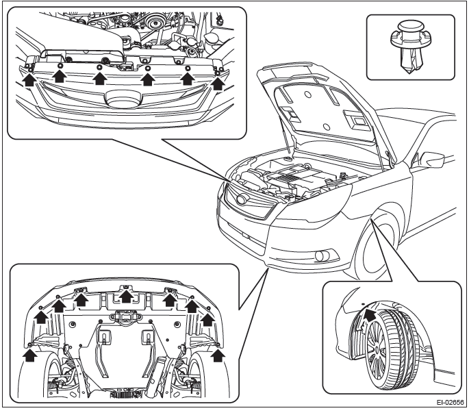
2) Remove the bumper face assembly.
- Remove the clips, turn over the front mud guard, and disconnect the fog light connector. (Model with fog light)
- Remove the clips at the upper side of the bumper.
- Remove the clips from the fender.
- Remove the clips at the lower side of bumper.
- Detach the flange section on the bumper face side from the bracket side front UPR.
CAUTION: Do not pull forcibly. It may damage the flange sections of the bumper face.
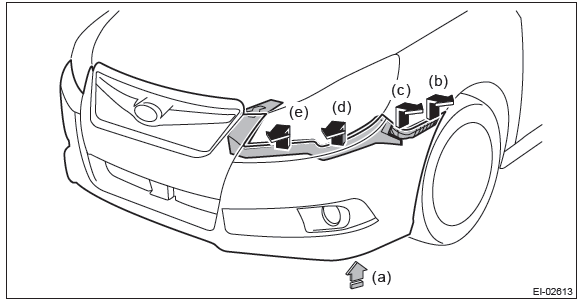
NOTE: Pushing up the lower side (a) of the fog light, remove from (b) to (e).
Detach the opposite side in the same manner.
3) Remove the clips and remove the air intake duct.

4) Remove the clips and remove the grille bracket.
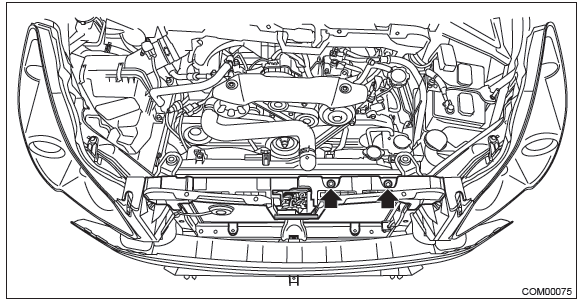
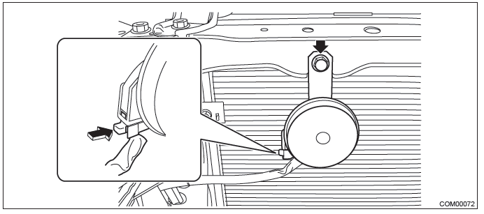
5) Remove the Lo pitch side horn.
- Disconnect the connector.
- Remove the horn bracket mounting bolt, and remove the Lo pitch side horn.
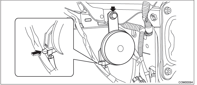
6) Remove the Hi pitch side horn.
- Disconnect the connector.
- Remove the horn bracket mounting bolt, and remove the Hi pitch side horn.
B: INSTALLATION
1) Install each part in the reverse order of removal.
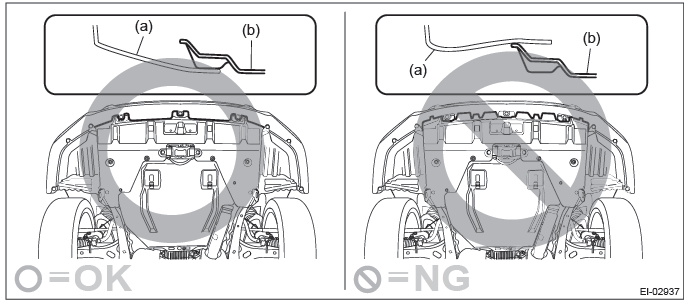
CAUTION: Install the bumper face so that the under cover front end (b) comes inside the front bumper face (a).
Tightening torque:
Horn assembly: 18 N*m (1.84 kgf-m, 13.3 ft-lb)
2) Adjust the fog light beam. (Model with fog light) <Ref. to LI-41, FOG LIGHT AIMING, ADJUSTMENT, Front Fog Light Assembly.>
C: INSPECTION
1. CHECK HORN ASSEMBLY.
1) Remove the horn assembly (Hi pitch side and Lo pitch side). <Ref. to COM-5, REMOVAL, Horn.>
2) Check the horn sounds when applying the battery voltage to the horn assembly.
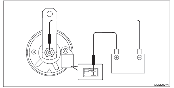

3) If it does not operate normally, replace the horn assembly.
Horn Switch
A: REMOVAL
NOTE: Horn switch is a unit with the driver's airbag module.
1) Position the front wheels straight ahead. (After moving a vehicle 5 m (16 ft) or more with front wheels positioned straight ahead, make sure that the vehicle moves straight ahead.)
2) Turn the ignition switch to OFF.
3) Disconnect the ground cable from battery and wait for at least 60 seconds before starting work.
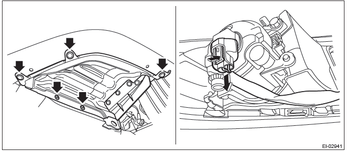
4) Remove the driver's airbag module assembly.
CAUTION: Before handling the airbag module, refer to "CAUTION" of "General Description" in "AIRBAG SYSTEM".
<Ref. to AB-9, CAUTION, General Description.>
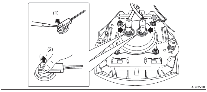
- Using a hexagon wrench etc. wrapped by protective tape, insert the snap pins and release the locks (3 locations).
- Disconnect the horn harness and airbag connector and remove the airbag module assembly. <Ref. to AB-18, PROCEDURE, Airbag Connector.>
B: INSTALLATION
CAUTION:
- Before handling the airbag module, refer to "CAUTION" of "General
Description" in "AIRBAG SYSTEM".
<Ref. to AB-9, CAUTION, General Description.>
- Do not allow harness and connectors to interfere or get tangled up with other parts.
1) Install the driver's airbag module. <Ref. to AB-36, INSTALLATION, Driver's Airbag Module.>
2) Install each part in the reverse order of removal.
C: INSPECTION
1. CHECK HORN SWITCH.
1) Remove the horn switch. <Ref. to COM-11, REMOVAL, Horn Switch.>
2) Check that the connection of the horn switch harness connector is correct.
3) Disconnect the horn switch harness connector and check the resistance between the harness connectors.
Preparation tool: Circuit tester
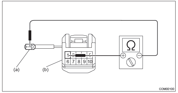
- Ground terminal
- Horn switch terminal

4) Replace the driver's airbag module if the inspection result is not within the standard value.
2. CHECK ROLL CONNECTOR.
1) Remove the roll connector. <Ref. to AB-96, REMOVAL, Roll Connector.>
2) Check the resistance between roll connector terminals.
Preparation tool: Circuit tester
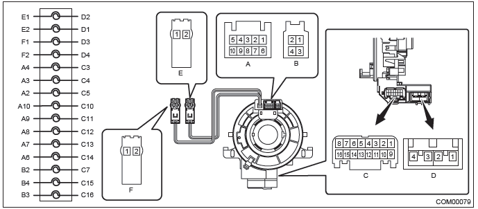

3) Replace the roll connector if the inspection result is not within the standard value.
READ NEXT:
 General Description of Glass, Windows, Mirrors
A: COMPONENT
1. FIXED GLASS (SEDAN MODEL)
Windshield glass
Dam rubber
Molding
Seal upper side
Locating pin
Rearview mirror mount
Rear window glass
Seal A
Relay and Fuse, Power Window System
A: LOCATION
NOTE: For other related fuses, refer to the wiring diagram. <Ref. to WI-15, Power Supply Circuit.>
B: INSPECTION
1. CHECK FUSE.
1) Remove the fuse and check visually.
2) If
SEE MORE:
Power Steering Oil Pump
A: REMOVAL
1) Disconnect the ground cable from battery.
2) Remove the V-belts. <Ref. to ME(H4SO)-43, REMOVAL, V-belt.>
3) Remove the power steering oil pump assembly.
Disconnect the connector from power steering pump switch.
Disconnect the pressure hose (b) and suction hose (a)
Rear gate (Outback)
The rear gate can be locked and unlocked using any of the following systems.
● Power door locking switch: Refer to “Power door locking switches” F2-7.
● Remote keyless entry system: Refer to “Remote keyless entry system” F2-8.
To open:
First unlock the rear gate lock then p
