Subaru Outback (BR): Cruise Control System
General Description
A: COMPONENT
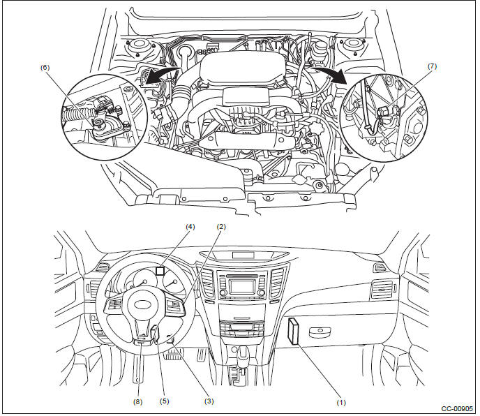
- Engine control module (ECM)
- Cruise control command switch
- Stop light and brake switch
- Cruise indicator light and cruise set indicator light
- Transmission control module (TCM) (AT and CVT model)
- Inhibitor switch (CVT model)
- Neutral position switch (MT model)
- Clutch switch (MT model)
NOTE: Inhibitor switch for 5AT model is installed on the valve body assembly.
B: CAUTION
- Before disassembling or reassembling parts, always disconnect the
battery ground cable from battery.
When replacing the audio, control module and other parts provided with memory functions, record the memory contents before disconnecting the battery ground cable. Otherwise, the memory is cleared.
- Reassemble the parts in the reverse order of disassembly procedure unless otherwise indicated.
- Adjust parts to the given specifications.
- Connect the connectors securely during reassembly.
- After reassembly, make sure that the functional parts operate normally.
- Yellow connectors and harnesses with yellow tapes around them are the connectors and harnesses for the airbag system. Using a tester above such circuits may cause malfunction of airbag system. Follow the cautions for the airbag system in this case. <Ref. to AB-9, CAUTION, General Description.>
- Be careful not to damage the airbag system wiring harness when servicing electrical parts and switches.
C: PREPARATION TOOL

Relay and Fuse
A: LOCATION
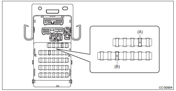

NOTE: For other related fuses, refer to the wiring diagram. <Ref. to WI-15, Power Supply Circuit.>
B: INSPECTION
1. CHECK FUSE.
1) Remove the fuse and inspect visually.
2) If the fuse is blown out, replace the fuse.
NOTE: If the fuse is blown again, check the system wiring harness.
Cruise Control System
A: WIRING DIAGRAM
Refer to "Cruise Control System" in the wiring diagram. <Ref. to WI-105, WIRING DIAGRAM, Cruise Control System.>
B: INSPECTION
Refer to "Basic Diagnostic Procedure" of "CRUISE CONTROL (DIAGNOSTICS)" section. <Ref. to CC(diag)- 2, Basic Diagnostic Procedure.>
C: NOTE
For operation procedures of each component of the cruise control system, refer to the respective section.
- Cruise control unit: <Ref. to CC-6, Cruise Control Module.>
- Cruise control command switch: <Ref. to CC-7, Cruise Control Command Switch.>
- Combination meter: <Ref. to CC-11, Combination Meter.>
- Stop light & brake switch: <Ref. to CC-12, Stop Light & Brake Switch.>
- Clutch switch: <Ref. to CC-13, Clutch Switch.>
- Inhibitor switch: <Ref. to CC-14, Inhibitor Switch.>
- Transmission control module (TCM): <Ref. to CC-15, Transmission Control Module (TCM).>
- Neutral position switch: <Ref. to CC-16, Neutral Position Switch.>
Cruise Control Module
A: NOTE
The control of cruise control system is carried out in engine control module (ECM).
B: REMOVAL
- H4 non-turbo model: <Ref. to FU(H4SO)-46, REMOVAL, Engine Control Module (ECM).>
- H4 turbo model: <Ref. to FU(H4DOTC)-58, REMOVAL, Engine Control Module (ECM).>
- H6 model: <Ref. to FU(H6DO)-54, REMOVAL, Engine Control Module (ECM).>
C: INSTALLATION
- H4 non-turbo model: <Ref. to FU(H4SO)-46, INSTALLATION, Engine Control Module (ECM).>
- H4 turbo model: <Ref. to FU(H4DOTC)-58, INSTALLATION, Engine Control Module (ECM).>
- H6 model: <Ref. to FU(H6DO)-54, INSTALLATION, Engine Control Module (ECM).>
Cruise Control Command Switch
A: REMOVAL
1) Position the front wheels straight ahead. (After moving a vehicle 5 m (16 ft) or more with front wheels positioned straight ahead, make sure that the vehicle moves straight ahead.)
2) Turn the ignition switch to OFF.
3) Disconnect the ground cable from battery and wait for at least 60 seconds before starting work.
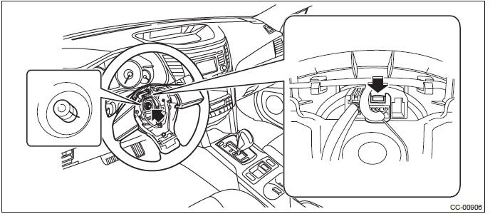
4) Remove the driver's airbag module assembly.
CAUTION: Before handling the airbag module, refer to "CAUTION" of "General Description" in "AIRBAG SYSTEM".
<Ref. to AB-9, CAUTION, General Description.>
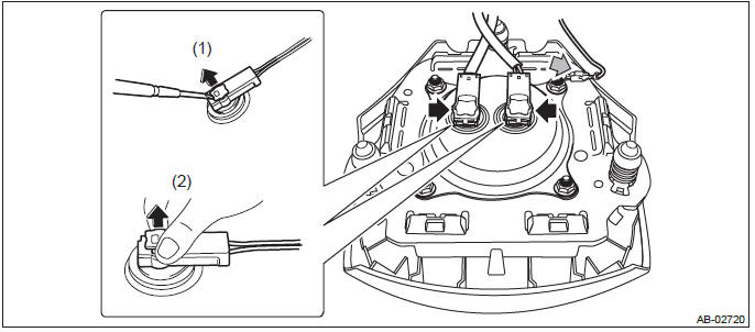
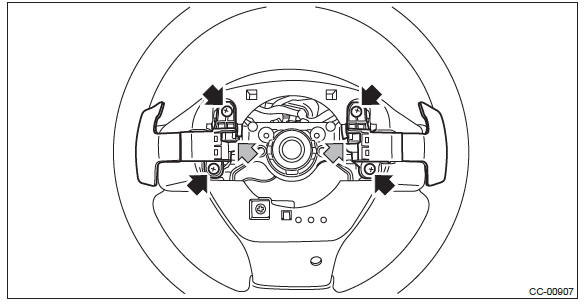
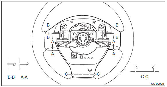
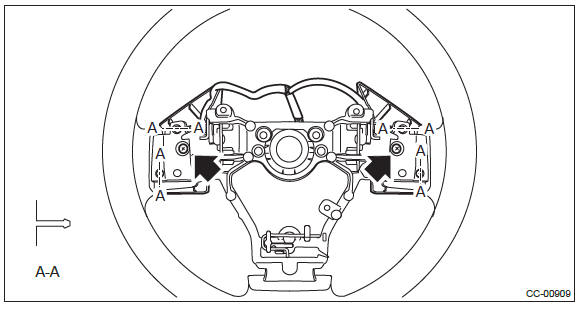
- Using a hexagon wrench etc. wrapped by protective tape, insert the snap pins and release the locks (3 locations).
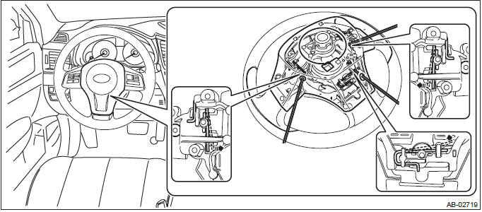
- Disconnect the horn harness and airbag connector and remove the airbag module assembly. <Ref. to AB-18, PROCEDURE, Airbag Connector.>
5) Remove the steering wheel.
CAUTION:
- Always use the steering wheel puller for removal to avoid deforming the steering wheel.
- If the steering wheel has been removed, make sure that the roll connector is not turned from the original position.
Preparation tool: Steering wheel puller
- Disconnect the connector and remove the nut.
- Put alignment marks and remove the steering wheel using a steering puller.
6) Remove the cruise control command switch.
- Remove the screw, disconnect the connector and remove the paddle shift switch. (Model with paddle shift)
- Disconnect the claws and then remove the lower cover.
- Remove the screw to remove the cruise control command switch assembly.
B: INSTALLATION
1) Install each part in the reverse order of removal.
CAUTION:
- Before handling the airbag module, refer to "CAUTION" of "General
Description" in "AIRBAG SYSTEM".
<Ref. to AB-9, CAUTION, General Description.>
- Do not allow harness and connectors to interfere or get tangled up with other parts.
2) Before installing steering wheel, be sure to adjust the direction of roll connector with steering. <Ref. to AB- 101, ADJUSTMENT, Roll Connector.>
Tightening torque:
Steering wheel: 39 N*m (3.98 kgf-m, 28.8 ft-lb)
Clearance:
Between column cover and steering wheel: 2 - 4 mm (0.08 - 0.16 in)
C: INSPECTION
1) Disconnect the cruise control command switch connector.
2) Check the resistance between cruise control command switch terminals.
Preparation tool: Circuit tester
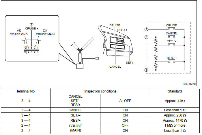
3) Replace the cruise control command switch if the inspection result is not within the standard value.
Combination Meter
A: NOTE
For the combination meter, refer to "INSTRUMENTATION/DRIVER INFO" section. <Ref. to IDI-21, Combination Meter.>
Stop Light & Brake Switch
A: NOTE
For stop light and brake switch, refer to "BRAKE" section. <Ref. to BR-66, INSPECTION, Stop Light Switch.>
Clutch Switch
A: NOTE
For clutch switch, refer to "CLUTCH" section. <Ref. to CL-31, Clutch Switch.>
Inhibitor Switch
A: NOTE
1. CVT MODEL
For inhibitor switch, refer to "CONTINUOUSLY VARIABLE TRANSMISSION" section. <Ref. to CVT-95, Inhibitor Switch.>
2. 5AT MODEL
Inhibitor switch cannot be removed and checked, because the inhibitor switch is installed on control valve assembly.
When a malfunction occurs, refer to "AUTOMATIC TRANSMISSION (DIAGNOSTICS)" section. <Ref. to 5AT(diag)-36, DTC P0705 TRANSMISSION RANGE SENSOR CIRCUIT (PRNDL INPUT), Diagnostic Procedure with Diagnostic Trouble Code (DTC).>
Transmission Control Module (TCM)
A: NOTE
For transmission control module (TCM), refer to following section.
- CVT model: <Ref. to CVT-124, Transmission Control Module (TCM).>
- 5AT model: <Ref. to 5AT-57, Transmission Control Module (TCM).>
Neutral Position Switch
A: NOTE
For neutral position switch, refer to "MANUAL TRANSMISSION AND DIFFERENTIAL" section. <Ref. to 6MT-37, Switches and Harness.>
READ NEXT:
 Cruise Control System (Diagnostics)
Basic Diagnostic Procedure
A: PROCEDURE
CAUTION:
When performing diagnosis, observe the legal speed limit on the road.
The cancel code will be also appear when cruise control is cancelled
by the
Immobilizer (Diagnostics)
Basic Diagnostic Procedure
A: PROCEDURE
General Description
A: CAUTION
CAUTION:
Do not use electrical test devices on any airbag
system wiring harnesses and connector
circuits.
Be careful not t
SEE MORE:
Front Vehicle Speed Sensor
A: REMOVAL
1) Remove the transmission assembly from the vehicle.
<Ref. to 5AT-37, REMOVAL, Automatic
Transmission Assembly.>
2) Disconnect the rear vehicle speed sensor connector.
NOTE:
Secure the transmission harness to the transmission
body using wire etc.
3) Remove the extension case.
Operation
If the driver and/or front passenger have/ has not yet fastened the seatbelt(s)
when the ignition switch is turned to the “ON” position, the seatbelt warning light(s)
will flash for 6 seconds, to warn that the seatbelt(s) is/are unfastened. If the
driver’s seatbelt is not fastened, a chi
