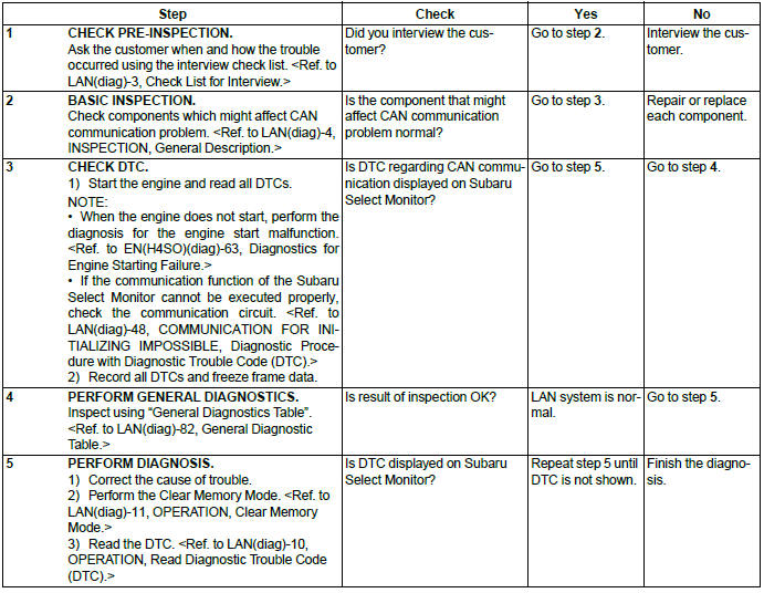
Subaru Outback (BR): Basic Diagnostic Procedure of LAN System
A: PROCEDURE
CAUTION:
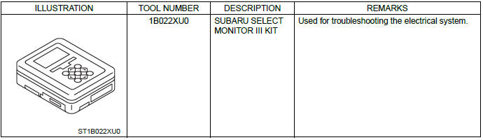
- Subaru Select Monitor is required for reading DTC, performing diagnosis, reading current data, customizing and active test (compulsory drive).
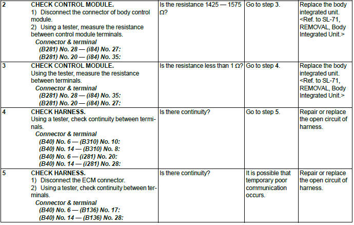
- Remove foreign matter (dust, water, oil, etc.) from each control module connector during removal and installation.
- For model with immobilizer or model with keyless access, registration of immobilizer may be needed after the replacement of controller etc. For details, refer to the "PC application help for Subaru Select Monitor".
NOTE:
- To check harness for open or short circuits, shake the suspected trouble spot or connector.
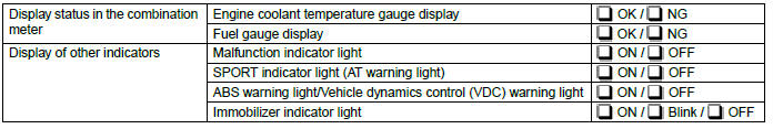
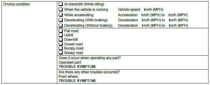
- Check List for Interview <Ref. to LAN(diag)-3, Check List for Interview.>
Check List for Interview
A: CHECK
Inspect the following item about the vehicle's state.
1. DISPLAY STATUS IN THE COMBINATION METER
2. CONDITIONS UNDER WHICH TROUBLE OCCURS
General Description
A: CAUTION
1. SUPPLEMENTAL RESTRAINT SYSTEM "AIRBAG"
Airbag system wiring harness is routed near the body integrated unit and twisted pair line.
CAUTION:
- Do not use the electrical test equipment on all airbag system wiring harnesses and connectors.
- Be careful not to damage the airbag system wiring harness when servicing the body integrated unit and LAN system.
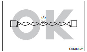
2. LAN SYSTEM
- Bus line of LAN system is twisted pair line. Be careful not to by-pass or partly unbind the twisted pair line.
- Do not make clearance between bus lines (CAN High, CAN Low).
- Difference of bus line length should be within 10 cm (3.94 in).
- Fray near the connector should be within 8 cm (3.14 in).
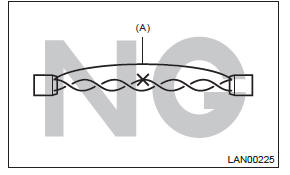
- Bypass wire connection
- If the characteristics of the twisted pair line are changed, it may extremely weaken against noise.
- When repairing the harness, connect the wires using soldering and protect it with insulating tape etc.
- Soldering and protection with insulating tape
B: INSPECTION
Before performing diagnostics, check the following item which might affect body integrated unit malfunctions.
1) Measure the battery voltage and check electrolyte.
Standard voltage: 12 V or more
Specific gravity: 1.260 or more
2) Check the fuse condition.
Make sure that ampere of the fuse is setting value, and it is not blown out.
3) Check the connecting condition of harness and harness connector.
4) Confirm settings of body integrated unit are corresponded to vehicle equipment. <Ref. to BC(diag)- 18, OPERATION, Registration Body Integrated Unit.>
5) Make sure that the User Customizing of the body integrated unit matches the vehicle equipment.
<Ref. to BC(diag)-16, OPERATION, User Customizing.>
6) Confirm "Factory initial setting" of body integrated unit registrations is set to "Market".
7) Confirm key illumination does not blink with ignition switch turned to ON.
C: PREPARATION TOOL
1. SPECIAL TOOL
2. GENERAL TOOL

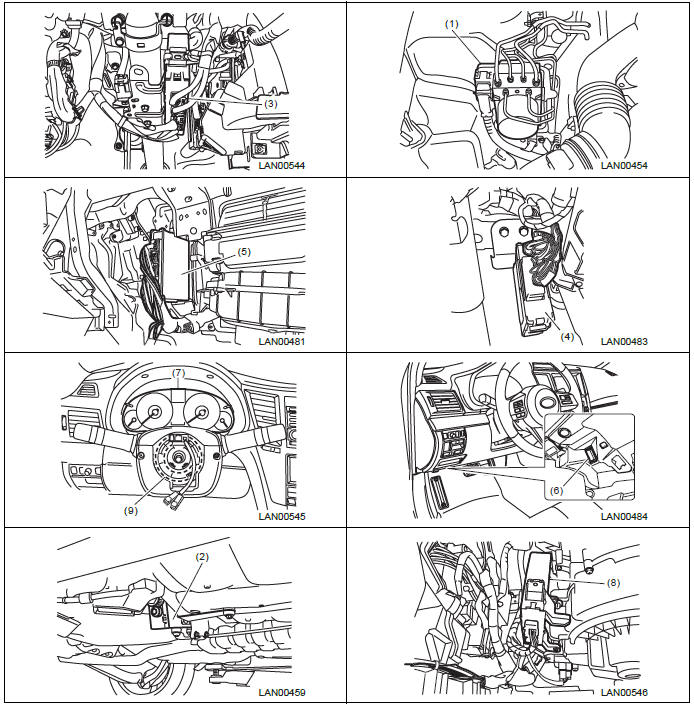
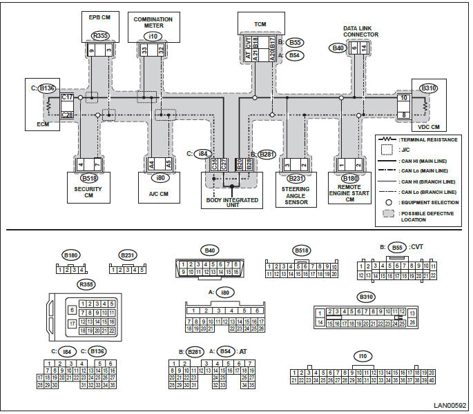
Electrical Component Location
A: LOCATION
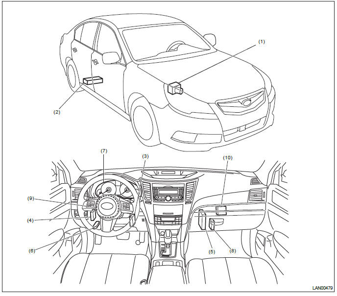
- ABSCM&H/U or VDCCM&H/U (inside engine room)
- Electronic parking CM
- Body integrated unit
- Transmission control module (AT)
- Engine control module
- Data link connector
- Combination meter
- A/C CM
- Steering angle sensor
- Security CM
Control Module I/O Signal
A: ELECTRICAL SPECIFICATION
- Body integrated unit
For I/O signals of the body integrated unit, refer to Body Control (Diagnostics). <Ref. to BC(diag)-7, Control Module I/O Signal.>
- Engine control module
For I/O signals of ECM, refer to Engine (Diagnostics). <Ref. to EN(H4SO)(diag)-17, Engine Control Module (ECM) I/O Signal.> <Ref. to EN(H4DOTC)(diag)-18, Engine Control Module (ECM) I/O Signal.> <Ref. to EN(H6DO)(diag)-18, Engine Control Module (ECM) I/O Signal.>
- Transmission control module
For I/O signals of TCM, refer to Automatic Transmission (Diagnostics). <Ref. to 5AT(diag)-13, Transmission Control Module (TCM) I/O Signal.> <Ref. to CVT(diag)-11, Transmission Control Module (TCM) I/O Signal.>
- VDC control module
For I/O signals of VDC CM, refer to Vehicle Dynamics Control (Diagnostics). <Ref. to VDC(diag)-12, Control Module I/O Signal.>
- Electronic parking CM
For I/O signals of electronic CM, refer to Parking Brake (Diagnostics). <Ref. to PB(diag)-12, Control Module I/O Signal.>
- A/C CM
For unit I/O signals of A/C CM, refer to HVAC System (Diagnostics). <Ref. to AC(diag)-6, Control Module I/ O Signal.>
- Combination meter
For I/O signals of combination meter, refer to Combination Meter System. <Ref. to WI-98, WIRING DIAGRAM, Combination Meter System.>
- Data link connector
For I/O signals of data link connector, refer to Engine (Diagnostics). <Ref. to EN(H4SO)(diag)-27, Data Link Connector.> <Ref. to EN(H4DOTC)(diag)-29, Data Link Connector.> <Ref. to EN(H6DO)(diag)-28, Data Link Connector.>
* CAN sleep state: Hold on for approx. one minute with ignition OFF and the doors, trunk, rear gate all closed.
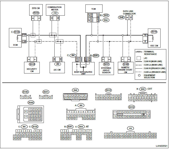
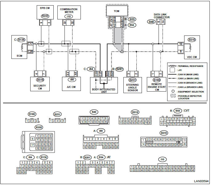
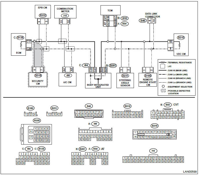
B: WIRING DIAGRAM
<Ref. to WI-85, WIRING DIAGRAM, CAN Communication System.>
Subaru Select Monitor
A: OPERATION
For details of basic operations, refer to "PC application help for Subaru Select Monitor".
Read Diagnostic Trouble Code (DTC)
A: OPERATION
For details of operation procedures, refer to "PC application help for Subaru Select Monitor".
Clear Memory Mode
A: OPERATION
For details of operation procedures, refer to "PC application help for Subaru Select Monitor".
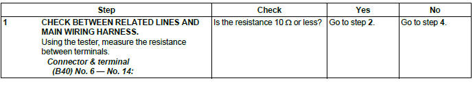
CAN Communication Circuit Check
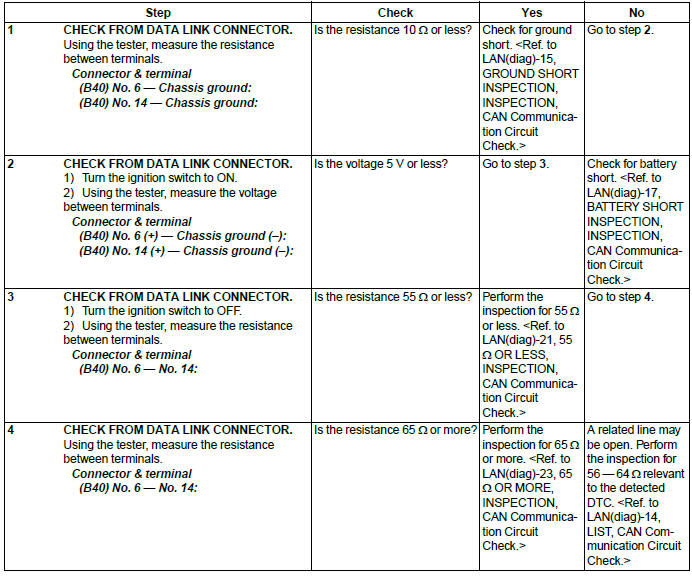
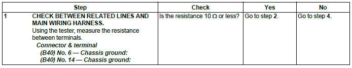
A: PROCEDURE
NOTE: When measuring the resistance of CAN communication circuit, measure it in sleep status.
To enter sleep status
- With ignition switch OFF and key or switch operation stopped, keep the doors, trunk, and rear gate all closed for one minute or more.
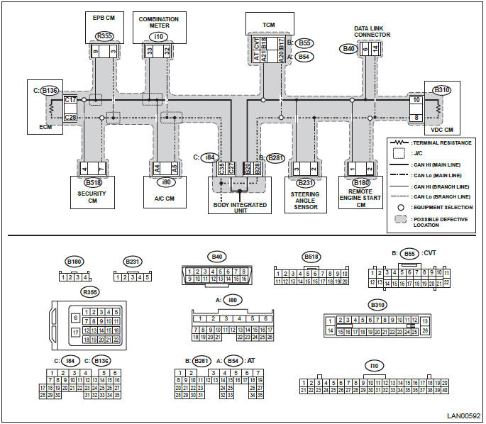
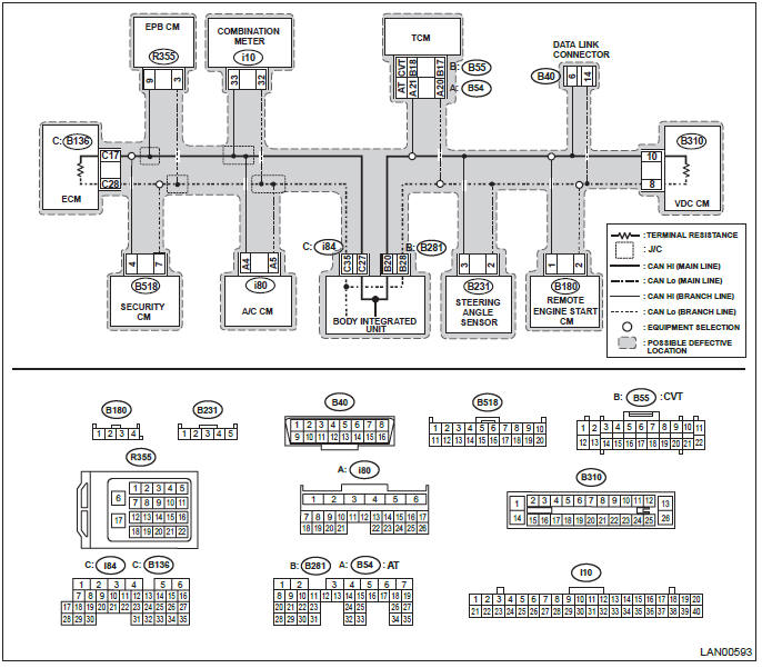
WIRING DIAGRAM:
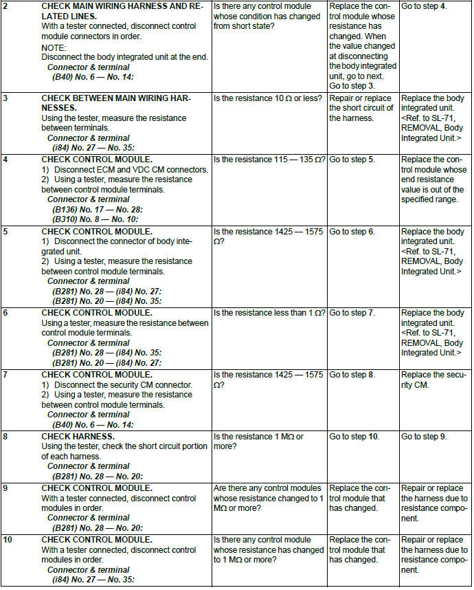
B: LIST
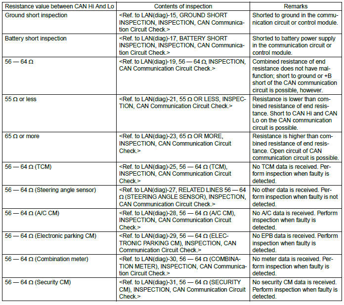
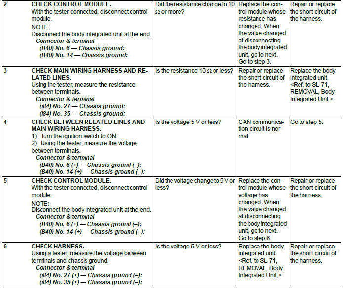
C: INSPECTION
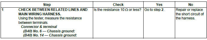
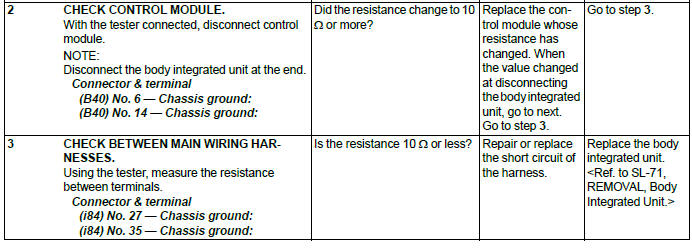
1. GROUND SHORT INSPECTION
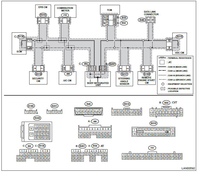
WIRING DIAGRAM:
NOTE: Main wiring harness or related lines may be shorted to ground, or shorted to ground in one of the control modules.
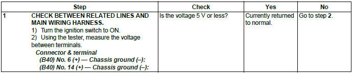
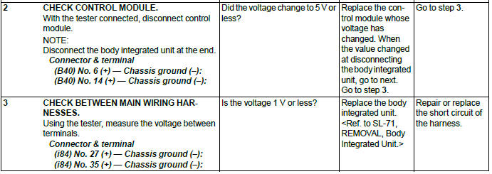
2. BATTERY SHORT INSPECTION
WIRING DIAGRAM:

NOTE: Main wiring harness or related lines may be shorted to battery circuit, or shorted to battery circuit in one of the control modules.
3. 56 - 64 Ω
WIRING DIAGRAM:
NOTE: When the measured resistance value is 56 - 64 Ω, main wiring harness or related lines may be shorted to ground, or shorted to power supply line, or related line may be open.
4. 55 Ω OR LESS
WIRING DIAGRAM:
NOTE: When the bus line is measured, combined resistance of end resistance (120 Ω) in ECM and end resistance (120 Ω) in VDC CM can be measured. The combined resistance is approximately 56 - 64 Ω. When the measured resistance value is 55 Ω or less, main wiring harness or related lines may be shorted, or combined resistance may have changed because resistance other than end resistance is created on the circuit.
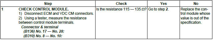
5. 65 Ω OR MORE
WIRING DIAGRAM:
NOTE: When CAN communication circuit is measured, combined resistance of end resistance (120 Ω) in ECM and end resistance (120 Ω) in VDC CM can be measured. The combined resistance is approximately 56 - 64 Ω.
When the measured resistance value is 65 Ω or more, either of end resistance or main wiring harness may have malfunction such as open circuit.
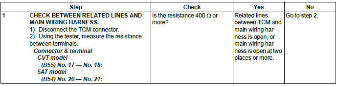
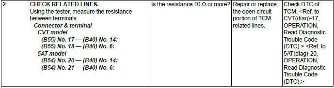
6. 56 - 64 Ω (TCM)
WIRING DIAGRAM:
NOTE: Perform inspection when no data is received, or faulty is detected. This is different from power supply shorted or ground shorted.
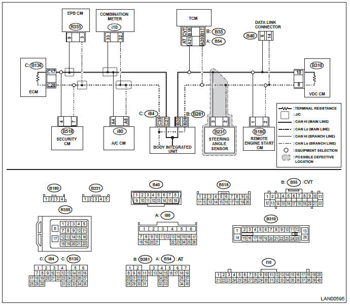
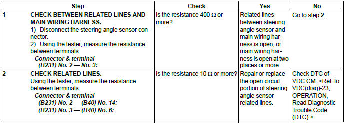
7. RELATED LINES 56 - 64 Ω (STEERING ANGLE SENSOR)
WIRING DIAGRAM:
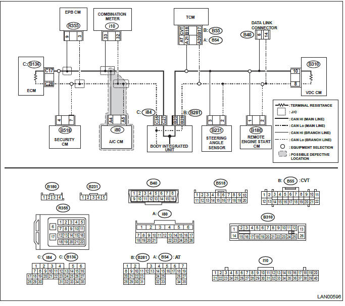
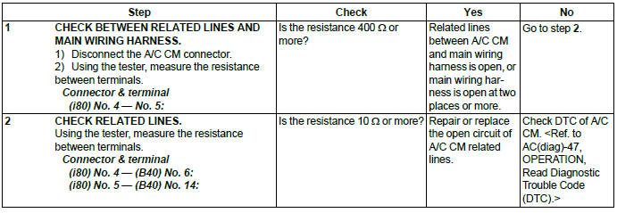
8. 56 - 64 Ω (A/C CM)
WIRING DIAGRAM:
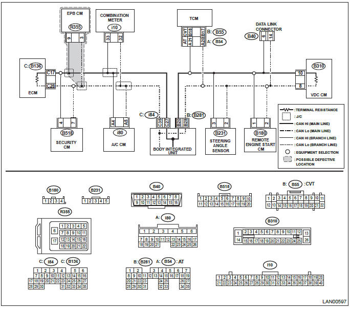
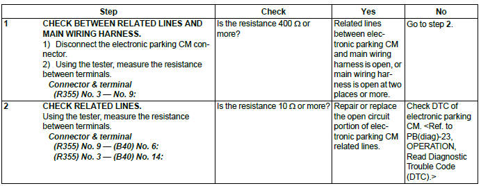
9. 56 - 64 Ω (ELECTRONIC PARKING CM)
WIRING DIAGRAM:
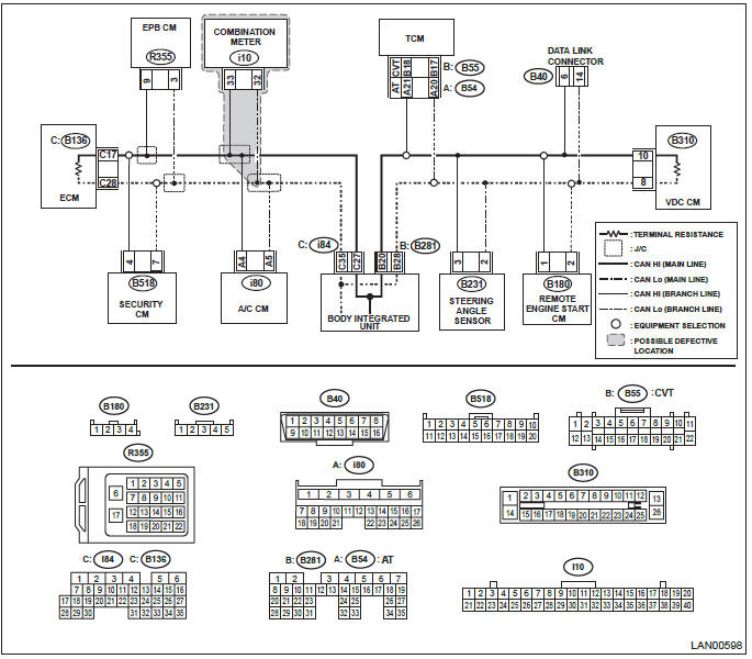
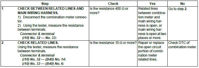
10.56 - 64 Ω (COMBINATION METER)
WIRING DIAGRAM:
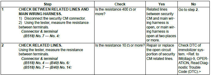
11.56 - 64 Ω (SECURITY CM)
WIRING DIAGRAM:
READ NEXT:
 LAN System - List of Diagnostic Trouble Code (DTC)
A: LIST
1. DTC TABLE
NOTE: When more than one DTC codes are recorded, referring to their combination and indicator display in the combination meter will make it easy to identify the possible caus
Basic Diagnostic Procedure of Body Control System
A: PROCEDURE
CAUTION:
Subaru Select Monitor is required for reading DTC, performing diagnosis and reading current data.
Remove foreign matter (dust, water, oil, etc.) from the body in
SEE MORE:
Headlight Bulb
A: REMOVAL
1. HIGH BEAM
CAUTION:
Because the halogen bulb operates at a high temperature, dirt and oil
on the bulb surface reduces
the bulb's service life. Hold the flange portion when replacing the bulb.
Never touch the glass portion.
Do not leave the headlight without a bulb for a long tim
General Description of Starting-Charging Systems
A: SPECIFICATION
1. 2.5 L MODEL
2. 3.6 L MODEL
B: COMPONENT
1. STARTER
Starter housing
Magnet switch ASSY
Shift lever
Starter seal
Overrunning clutch ASSY
Washer
Planetary gear
Starter plate
Yoke
Armature
Brush holder ASSY
Drain
