Subaru Outback (BR): Generator
A: REMOVAL
1) Disconnect the ground cable from battery.
2) Remove the V-belts. <Ref. to ME(H4SO)-43, VBELT, REMOVAL, V-belt.> <Ref. to ME(H4DOTC)-42, V-BELT, REMOVAL, V-belt.>
<Ref. to ME(H6DO)-51, REMOVAL, V-belt.>
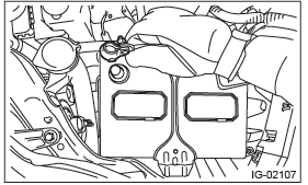
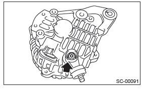
3) Disconnect the connector and terminal from generator.
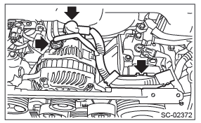
4) Remove the collector cover bracket or v-belt cover bracket.
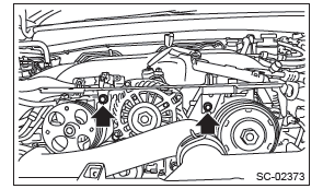
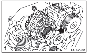
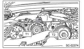
5) Remove the generator from the bracket.
B: INSTALLATION
Install in the reverse order of removal.
Tightening torque:
T1: 25 N*m (2.5 kgf-m, 18.4 ft-lb)
T2: 6.4 N*m (0.7 kgf-m, 4.7 ft-lb)
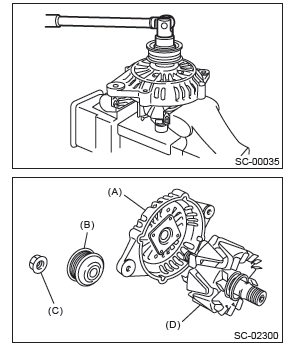
C: DISASSEMBLY
1. 2.5 L MODEL
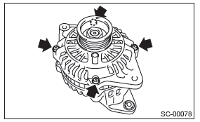
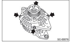
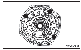
1) Remove the four through-bolts.
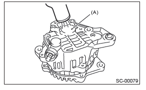
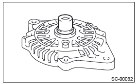
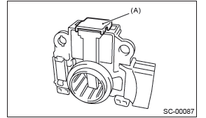
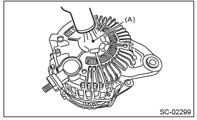
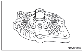
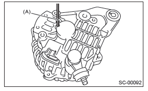
2) Use a drier to heat the rear cover (A) portion to 50ºC (122ºF).
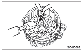
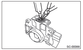
3) Insert the end of a flat tip screwdriver into the gap between stator core and front cover. Pry them apart to disassemble.
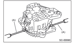
- Screwdriver
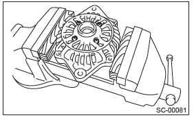
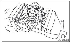
4) Using a vise, support the rotor and remove the pulley nut, then remove the rotor from the front cover.
CAUTION: When holding the rotor with a vise, place aluminum plates or wooden pieces on the vise jaws to prevent rotor from damage.
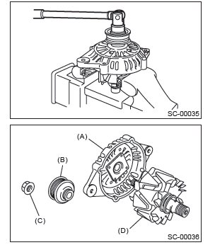
- Front cover
- Pulley
- Pulley nut
- Rotor
5) Use the following procedures to remove the ball bearings.
- Remove the bolt, and then detach the bearing retainer.
- Firmly attach an appropriate tool (such as a correct size socket wrench) to the bearing inner race.
- Use the press to push the ball bearings out from the front cover.
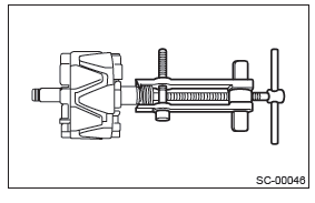
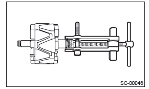
6) Using the bearing puller, remove the bearings from the rotor.
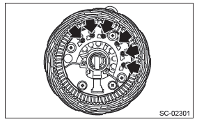
7) Disconnect the connection between the rectifier and stator coil, then remove the stator coil.
CAUTION: The rectifier is easily damaged by heat. Do not allow a 180 - 270 W soldering iron to contact the terminals for 5 seconds or more at a time.
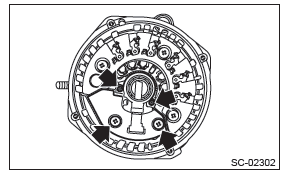
8) Use the following procedures to remove the IC regulator.
- Remove the screws which secure the IC regulator to the rear cover.
- Disconnect the connection between the IC regulator and rectifier, then remove the IC regulator.
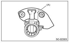
9) Use the following procedures to remove the brush.
- Remove the cover A.
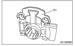
- Cover A
- Remove the cover B.
- Cover B
- Disconnect the connection and remove the brush.
10) Remove the rectifier as follows.
- Remove the bolts which secure the rectifier.
- Remove the cover on terminal B.
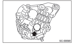
- Remove the nuts of terminal B, then remove the rectifier.
2. 3.6 L MODEL
1) Remove the four through-bolts.
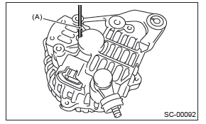
2) Use a drier to heat the rear cover (A) portion to 50 - 60ºC (122 - 140ºF).
3) Insert the end of a flat tip screwdriver into the gap between stator core and front cover. Pry them apart to disassemble.
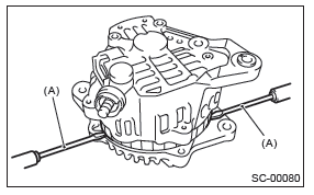
- Screwdriver
4) Using a vise, support the rotor and remove the pulley nut, then remove the rotor from the front cover.
CAUTION: When holding the rotor with a vise, place aluminum plates or wooden pieces on the vise jaws to prevent rotor from damage.
- Front cover
- Pulley
- Pulley nut
- Rotor
5) Use the following procedures to remove the ball bearings.
- Remove the bolt, and then detach the bearing retainer.
- Firmly attach an appropriate tool (such as a correct size socket wrench) to the bearing inner race.
- Use the press to push the ball bearings out from the front cover.
6) Using the bearing puller, remove the bearings from the rotor.
7) Remove six bolts between the rectifier and stator coil, then remove the stator coil.
8) Remove four screws which secure the IC regulator to the rear cover, then remove the IC regulator.
9) Use the following procedures to remove the brush.
- Remove the cover A.
- Cover A
- Remove the cover B.
- Cover B
- Disconnect the connection and remove the brush.
10) Remove the rectifier as follows.
- Remove the cover on terminal B.
- Remove the nut on terminal B.
- Remove the bolts which secure the rectifier, and remove the rectifier.
D: ASSEMBLY
1. 2.5 L MODEL
Assemble in the reverse order of disassembly.
NOTE:
- Refer to component for tightening torque of each part. <Ref. to SC(H4SO)-5, GENERATOR, COMPONENT, General Description.>
- After assembling, manually turn the pulley to check that the rotor rotates smoothly.
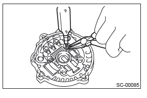
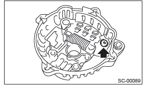
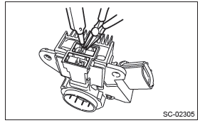
1) Push of the brush Before assembling the front and rear parts, press the brush down into the brush holder, then fix the brush in that position by inserting a [1 mm (0.04 in) dia., 40 - 50 mm (1.6 - 2.0 in) long] wire through the hole as shown in the figure.
CAUTION: After re-assembling, remove the wire.
- Wire
2) Install the ball bearings.
- Set the ball bearings in the front cover, then securely install an appropriate tool (such as a socket wrench of proper size) to the bearing outer race.
- Using a press to press the ball bearings into the specified location.
- Install the bearing retainer.
3) Use a press to install the bearings (rear side) to the rotor shaft.
4) Heat the bearing box in rear cover to 50 - 60ºC (122 - 140ºF), and then press the rear bearing into rear cover.
CAUTION: Do not apply grease to the rear bearings. If there is any oil on the bearing box, remove it completely.
2. 3.6 L MODEL
Assemble in the reverse order of disassembly.
NOTE:
- Refer to component for tightening torque of each part. <Ref. to SC(H4SO)-5, GENERATOR, COMPONENT, General Description.>
- After assembling, manually turn the pulley to check that the rotor rotates smoothly.
1) Push of the brush
Before assembling the front and rear parts, press the brush down into the brush holder, then fix the brush in that position by inserting a [1 mm (0.08 in) dia., 40 - 50 mm (1.6 - 2.0 in) long] wire through the hole as shown in the figure.
CAUTION: After re-assembling, remove the wire.
- Wire
2) Install the ball bearings.
- Set the ball bearings in the front cover, then securely install an appropriate tool (such as a socket wrench of proper size) to the bearing outer race.
- Using a press to press the ball bearings into the specified location.
- Install the bearing retainer.
3) Use a press to install the bearings (rear side) to the rotor shaft.
4) Heat the bearing box in rear cover to 50 - 60ºC (122 - 140ºF), and then press the rear bearing into rear cover.
CAUTION: Do not apply grease to the rear bearings. If there is any oil on the bearing box, remove it completely.
E: INSPECTION
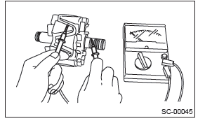
1. DIODE (2.5 L MODEL)
CAUTION: There is the possibility of damaging the diodes if a mega-tester (used to measure high voltages) or a similar measuring instrument is used.
Never use a mega tester or equivalent for this test.
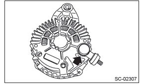
1) Check for continuity between the diode lead and positive side heat sink. If resistance is 1 Ω or more only in the direction from the diode lead to the heat sink, replace the rectifier.
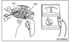
- Diode lead
- Heat sink (positive side)
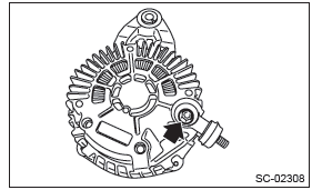
2) Check for continuity between the negative side heat sink and diode lead. If resistance is 1 Ω or more only in the direction from the heat sink to the diode lead, replace the rectifier.
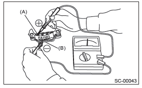
- Diode lead
- Heat sink (negative side)
2. DIODE (3.6 L MODEL)
CAUTION: There is the possibility of damaging the diodes if a mega-tester (used to measure high voltages) or a similar measuring instrument is used.
Never use a mega tester or equivalent for this test.
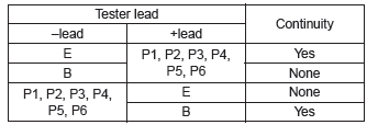
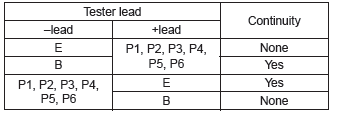
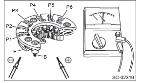
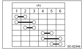
1) Check for continuity between the diode lead and terminal E or B. If continuity is not as shown in the table, replace the rectifier.
- At analog type tester
- At digital type tester
3. ROTOR
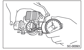
1) Inspect the slip rings for contamination or any roughness on the sliding surface. Repair the slip ring surface using a lathe or sand paper.
2) Measure the slip ring outer diameter. Replace the rotor if the slip ring is worn.
Slip ring outer diameter:
Standard
22.7 mm (0.894 in)
Limit
22.1 mm (0.870 in)
3) Using a circuit tester, check the resistance between slip rings. If resistance exceeds the standard, replace the rotor.
Standard: Approx. 1.8 - 2.2 Ω
4) Check the continuity between slip ring and rotor core or shaft. If there is continuity, replace the rotor because the rotor coil is grounded.
5) Check the ball bearings. If there is any noise, or the rotor does not rotate smoothly, replace the bearings.
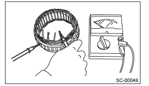
4. STATOR COIL (2.5 L MODEL)
1) Inspect continuity between the stator coil lead wire terminals. If the resistance is 1 MΩ or more, replace the stator coil.

- Stator
2) Inspect the continuity between the stator coil stator core and lead wire terminals. If the resistance is 1 Ω or less, replace the stator coil.
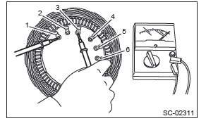
5. 3.6 L MODEL
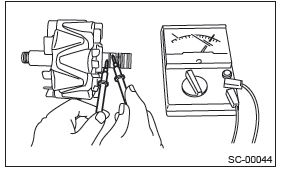
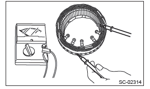
1) Continuity test
Inspect the continuity between the stator coil terminals.
If continuity is not as shown in the table, replace the stator coil.
- Terminals
2) Insulation test
Inspect the continuity between the stator coil stator core and lead wire terminals. If there is continuity, replace the stator coil because the stator coil is grounded.
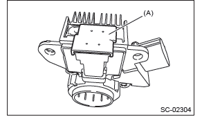
6. BRUSH
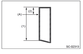
1) Measure the length of each brush. Replace the brush if wear exceeds service limits. There is a service limit mark (A) on each brush.
Brush length:
- 2.5 L model
Standard (1)
18.5 mm (0.728 in)
Limit (2)
5.0 mm (0.197 in) - 3.6 L model
Standard (1)
22.5 mm (0.886 in)
Limit (2)
5.0 mm (0.197 in)
2) Using a spring pressure indicator, push the brush into the brush holder until its tip protrudes 2 mm (0.08 in). Then measure the pressure of brush spring. If the pressure is 2.648 N (270 g, 9.52 oz) or less, replace the brush spring with a new part. 4.609 - 5.786 N (470 - 590 g, 16.58 - 20.810 oz) pressure is required on the new spring.
7. BALL BEARING
Check the ball bearings. Replace the ball bearings if there is resistance in the rotation, or if there is any abnormal noise.
8. OTHER INSPECTIONS
Check that the generator does not have deformation, cracks and any other damage.
READ NEXT:
 Battery (inspection, removal, installation)
A: REMOVAL
1) After disconnecting the battery ground terminal, remove the terminal cover, then disconnect the positive terminal.
2) Remove the battery cable holder from the battery rod.
3) Remove
Basic Diagnostic Procedure of Engine - H4SO
A: PROCEDURE
1. ENGINE
Check List for Interview
A: CHECK
1. CHECK LIST NO. 1
Check the following item when problem has occurred.
NOTE: Use copies of this page for interviewing customers.
SEE MORE:
DTC P0442, P0447, P0448, P0451, P0452, P0453, P0456, P0457, P0458, P0459,
P0461, P0462, P0463, P0464
BV:DTC P0442 EVAPORATIVE EMISSION CONTROL SYSTEM LEAK DETECTED
(SMALL LEAK)
1. OUTLINE OF DIAGNOSIS
The evaporative system monitor detects leak up to 0.020 inch in the fuel tank
and evaporative emissions system.
If the fuel cap is not present or has not been correctly tightened after a
refueling
Driving tips for AWD vehicles
WARNING
● Always maintain a safe driving speed according to the road and weather conditions
in order to avoid having an accident on a sharp turn, during sudden braking or under
other similar conditions.
● Always use the utmost care in driving – overconfidence because you are driv
