Subaru Outback manuals

Subaru Outback (BR): Replacing the air cleaner element

Replace the air cleaner element according to the maintenance schedule in the “Warranty and Maintenance Booklet”. Under extremely dusty conditions, replace it more frequently. It is recommended that you always use genuine SUBARU parts.

Non-turbo models
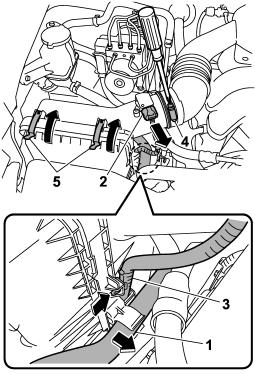
1) Hydraulic hose


1) Hydraulic hose
2) Connector
3) Connector cable
4) Clamp
5) Clips

1. Remove the hydraulic hose in the power steering system from the clip on the right side of the air cleaner case.

2. Unplug the connector that is attached to the top of the air cleaner case.

3. To remove the connector cable from the air cleaner case, remove the clip that is attached to the connector cable from the guide lug on the right side of the air cleaner case.

4. Loosen the screw on the clamp.

5. Unsnap the two clips holding the air cleaner case cover.
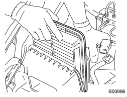
6. Open the air cleaner case and remove the air cleaner element.


6. Open the air cleaner case and remove the air cleaner element.

7. Clean the inside of the air cleaner case and case cover with a damp cloth and install a new air cleaner element.
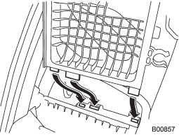
8. To install the air cleaner case, insert the three projections on the air cleaner


8. To install the air cleaner case, insert the three projections on the air cleaner case into the slits on the air cleaner case cover.

9. Install the removed or loosened parts in the reverse order of removal.

READ NEXT:

 Turbo models

1) Air intake duct 2) Air cleaner case 3) Clamp 1. Remove the hydraulic hose in the power steering system from the clip on the air intake duct. 2. Remove the hydraulic hose from the clip on the

 Spark plugs

It may be difficult to replace the spark plugs. It is recommended that you have the spark plugs replaced by your SUBARU dealer. The spark plugs should be replaced according to the maintenance sched

 Recommended spark plugs

Refer to “Electrical system” F12-8.

SEE MORE:

 Tachometer

The tachometer shows the engine speed in thousands of revolutions per minute. CAUTION Do not operate the engine with the pointer of the tachometer in the red zone. In this range, fuel injection will be cut by the engine control module to protect the engine from overrevving. The engine will res

 Multi function display

1) Multi function display switching knob With the ignition switch in the “ON” position, each successive press of the multi function display switching knob toggles the display in the following sequence.

© 2010-2025 Copyright www.suoutback.com