Subaru Outback (BR): Basic Diagnostic Procedure of Engine - H4SO
A: PROCEDURE
1. ENGINE
Check List for Interview
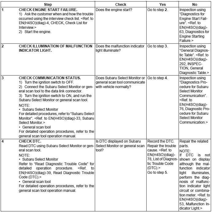
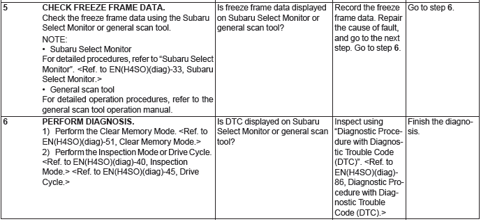
A: CHECK
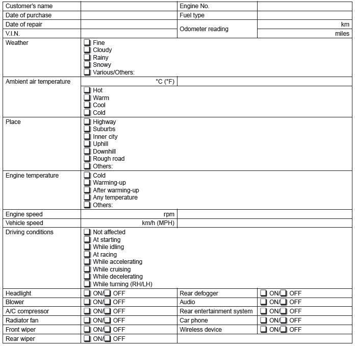
1. CHECK LIST NO. 1
Check the following item when problem has occurred.
NOTE: Use copies of this page for interviewing customers.
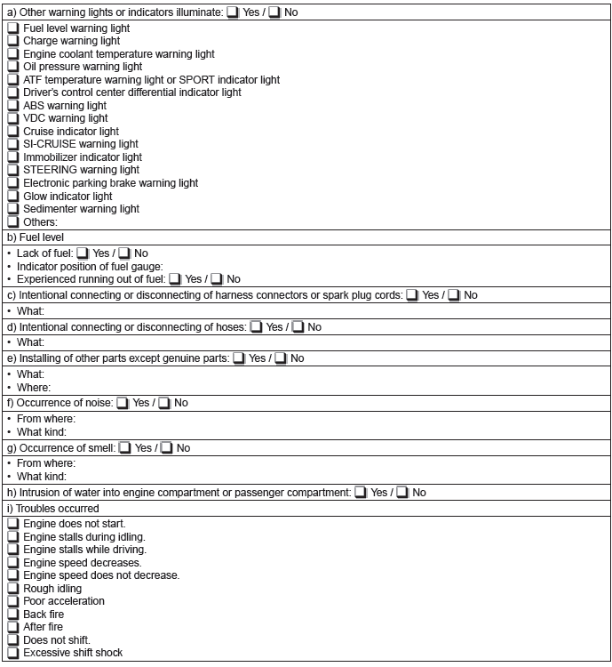
2. CHECK LIST NO. 2
Check the following item about the vehicle's state when the malfunction indicator light turns on.
NOTE: Use copies of this page for interviewing customers.
General Description
A: CAUTION
1) Airbag system wiring harness is routed near the ECM, main relay and fuel pump relay.
CAUTION:
- Do not use electrical test equipment on the airbag system circuits.
- Be careful not to damage the airbag system wiring harness when servicing the ECM, TCM, main relay and fuel pump relay.
2) Never connect the battery in reverse polarity.
Doing so will damage the ECM instantly, and other parts will also be damaged.
3) Do not disconnect the battery terminals while the engine is running. A large counter electromotive force will be generated in the generator, and this voltage may damage electronic parts such as ECM etc.
4) Before disconnecting the connectors of each sensor and ECM, be sure to turn the ignition switch to OFF. Perform the Clear Memory Mode after connecting the connectors. <Ref. to EN(H4SO)(diag)- 51, Clear Memory Mode.>
5) When measuring the voltage or resistance of individual sensor or all electrical control modules, use a tapered pin with a diameter of less than 0.6 mm (0.024 in). Do not insert the pin 4 mm (0.16 in) or more into the part.
CAUTION: When replacing the ECM, be careful not to use the wrong spec. ECM to avoid any damage on the fuel injection system.
NOTE: When replacing the ECM of the models with Immobilizer, immobilizer system must be registered. To do so, all ignition keys and ID cards need to be prepared.
Refer to the "PC application help for Subaru Select Monitor".
6) Take care not to allow water to get into the connectors when servicing or washing the vehicle in rainy weather. Avoid exposure to water even if the connectors are waterproof.
7) Use ECM mounting stud bolts at the body side grounding point when measuring voltage and resistance inside the passenger compartment.
- Stud bolt
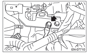
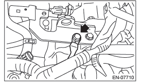
8) Use the engine ground terminal or engine assembly for the grounding point to chassis when measuring the voltage and resistance in engine compartment.
9) Every engine control system-related part is a precision part. Do not drop them.
10) Observe the following cautions when installing a radio in vehicle.
CAUTION:
- The antenna must be kept as far apart as possible from control module. (ECM is installed at the back of the glove box.)
- The antenna feeder must be placed as far apart as possible from the ECM and engine control system harness.
- Carefully adjust the antenna for correct matching.
- When mounting a large power type radio, pay special attention to the three items mentioned above.
- Incorrect installation of the radio may affect the operation of ECM.
11) When disconnecting the fuel hose, release the fuel pressure. <Ref. to FU(H4SO)-53, RELEASING OF FUEL PRESSURE, PROCEDURE, Fuel.>
12) Warning lights may illuminate when performing driving test with jacked-up or lifted-up condition, but this is not a system malfunction. The reason for this is the speed difference between the front and rear wheels. When engine control system diagnosis is finished, perform the VDC memory clearance procedure of self-diagnosis function. <Ref. to VDC(diag)- 25, Clear Memory Mode.>
B: INSPECTION
Before performing diagnostics, check the following item which might affect engine problems.
1. BATTERY
1) Measure the battery voltage and specific gravity of the electrolyte.
Standard voltage: 12 V
Specific gravity: 1.260 or more
2) Check the condition of the main and other fuses, and harnesses and connectors. Also check for proper grounding.
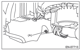
2. ENGINE GROUND
Make sure that the engine ground terminal has no contamination, corrosion or looseness and is properly connected to the engine.
C: NOTE
- The on-board diagnostic (OBD) system detects and indicates a fault in various inputs and outputs of the complex electronic control. Malfunction indicator light in the combination meter indicates occurrence of a fault or trouble.
- Further, against such a failure of sensors as may disable the drive, the fail-safe function is provided to ensure the minimal drivability.
- The OBD system incorporated with the vehicles within this type of engine complies with OBD-II regulations.
The OBD system monitors the components and the system malfunction listed in "Engine Section" which affects on emissions.
- When the system decides that a malfunction occurs, malfunction indicator light illuminates. At the same time of the malfunction indicator light illumination or blinking, a DTC and a freeze frame engine conditions are stored into on-board computer.
- The OBD system stores freeze frame engine condition data (engine load, engine coolant temperature, fuel trim, engine speed and vehicle speed, etc.) into on-board computer when it detects a malfunction.
- Freeze frame engine condition data are stored until the DTCs are cleared. However when such malfunctions as fuel trim fault and misfire are detected with the freeze frame engine condition data stored, they are rewritten into those related to the fuel trim fault and misfire.
- When the malfunction does not occur again for three consecutive driving cycles*, malfunction indicator light is turned off, but DTC remains at onboard computer.
*: One driving cycle means the period between the ignition switch ON and the ignition switch OFF after driving.
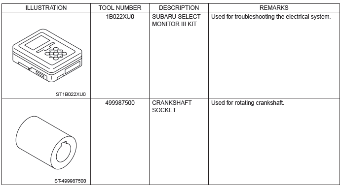
- When performing diagnosis, connect the Subaru Select Monitor or general scan tool to the vehicle.
D: PREPARATION TOOL
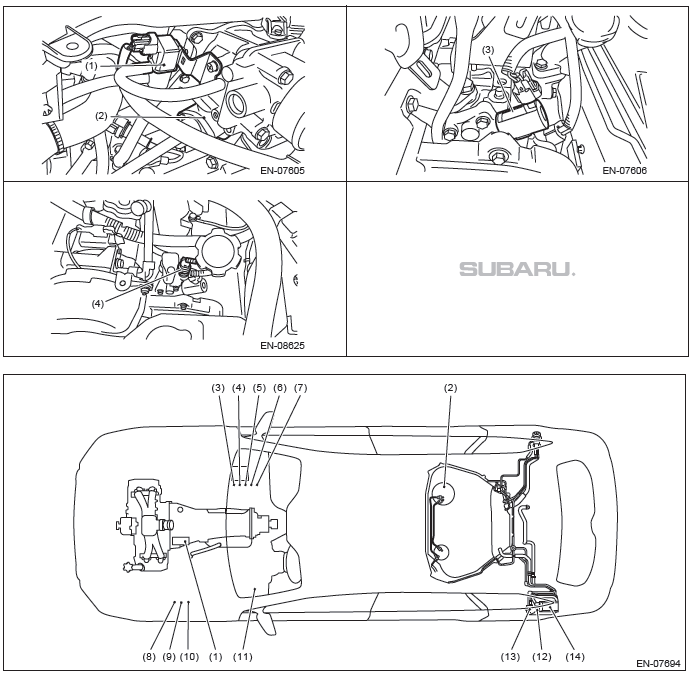
Electrical Component Location
A: LOCATION
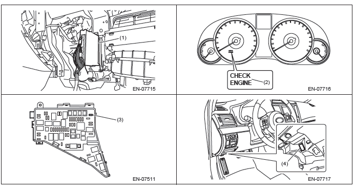
1. CONTROL MODULE
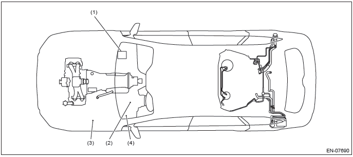
- Engine control module (ECM)
- Malfunction indicator light
- Delivery (test) mode fuse
- Data link connector
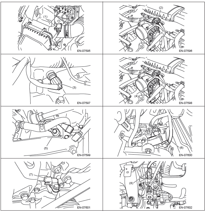
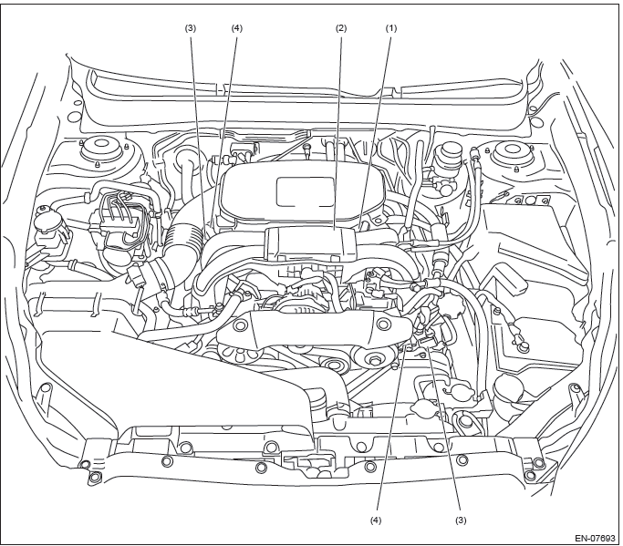
2. SENSOR
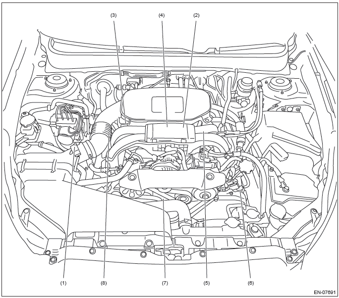
- Mass air flow and intake air temperature sensor
- Manifold absolute pressure sensor
- Engine coolant temperature sensor
- Electronic throttle control
- Knock sensor
- Camshaft position sensor
- Crankshaft position sensor
- Engine oil temperature sensor
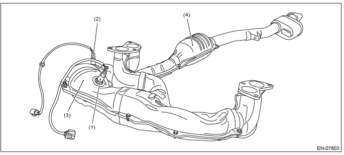
- Front oxygen (A/F) sensor
- Rear oxygen sensor
- Front catalytic converter
- Rear catalytic converter
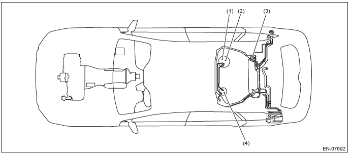
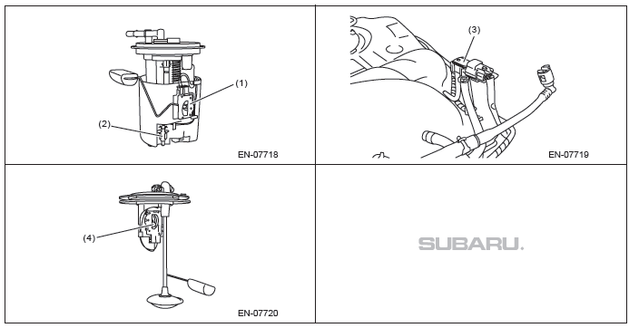
- Fuel level sensor
- Fuel temperature sensor
- Fuel tank pressure sensor
- Fuel sub level sensor
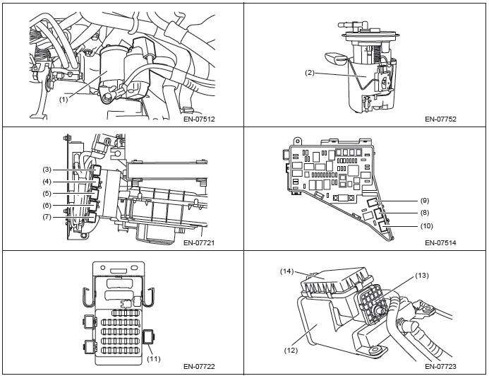
3. SOLENOID VALVE, ACTUATOR, EMISSION CONTROL SYSTEM PARTS AND IGNITION SYSTEM PARTS
- Purge control solenoid valve
- EGR control valve
- Oil switching solenoid valve
- Variable valve lift diagnosis oil pressure switch
- Starter
- Fuel pump
- Main relay
- IG relay
- A/F, oxygen sensor relay
- Electronic throttle control relay
- Fuel pump relay
- Radiator main fan relay 1
- Radiator main fan relay 2
- Radiator sub fan relay
- Starter relay
- Canister
- Drain valve
- Drain filter
4. TRANSMISSION
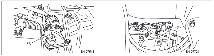
- Inhibitor switch (CVT model)
- Neutral position switch (MT model)
READ NEXT:
 Engine Control Module (ECM) I/O Signal
A: ELECTRICAL SPECIFICATION
Input/output name:
Crankshaft position sensor
Camshaft position sensor
Measuring condition:
After warming-up
At idling
Engine Condition Data
A: ELECTRICAL
Inspection Mode
A: PROCEDURE
Perform the diagnosis shown in the following DTC table.
When performing the diagnosis not listed in "List of Diagnostic Trouble Code (DTC)",
refer to the item on the
drive cycle. <Re
Drive Cycle
A: PROCEDURE
It is necessary to perform the drive cycle listed below if DTC is not found
in the Inspection Mode. It is possible
to complete diagnosis of the DTC by performing the indicated drive cycl
SEE MORE:
General Description of Drive Shaft System
A: SPECIFICATION
1. PROPELLER SHAFT
2. FRONT DRIVE SHAFT ASSEMBLY
Axle diameter
Axle length
3. REAR DRIVE SHAFT ASSEMBLY
Axle diameter
Axle length
B: COMPONENT
1. PROPELLER SHAFT
Propeller shaft
Rear differential (VA1-type)
Rear differe
Photosensors in the mirror
The Subaru Outback (BR) features a mirror equipped with photosensors on both its front and rear sides. These sensors are designed to detect bright glare from headlights of vehicles behind you during nighttime driving. As a safety measure, the mirror automatically dims to reduce glare and ensure
