Subaru Outback (BR): Inspection Mode
A: PROCEDURE
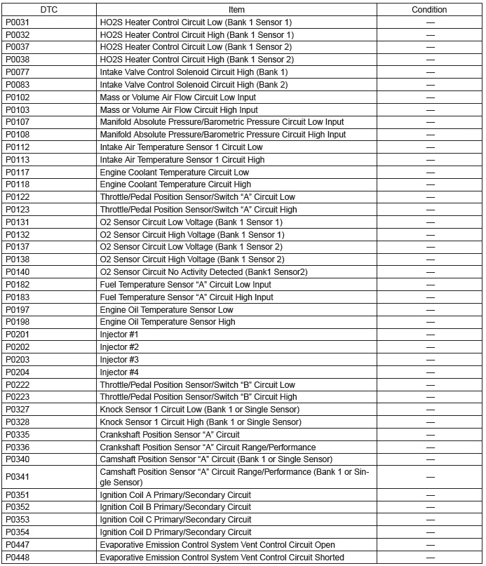
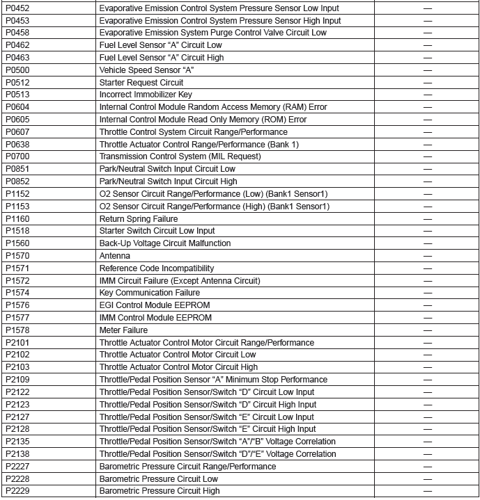
Perform the diagnosis shown in the following DTC table.
When performing the diagnosis not listed in "List of Diagnostic Trouble Code (DTC)", refer to the item on the drive cycle. <Ref. to EN(H4SO)(diag)-45, Drive Cycle.>
1. PREPARATION FOR THE INSPECTION MODE
1) Check that the battery voltage is 12 V or more
and fuel remains approx. half [20 - 40  (5.3 -
10.6 US gal, 4.4 - 8.8 Imp gal) ].
(5.3 -
10.6 US gal, 4.4 - 8.8 Imp gal) ].
2) Lift up the vehicle using a garage jack and place it on rigid racks, or drive the vehicle onto free rollers.
WARNING:
- Before lifting up the vehicle, ensure parking brake is applied.
- Do not use a pantograph jack in place of a rigid rack.
- Secure a rope or wire to the front or rear towing hooks to prevent the lateral runout of front wheels.
- Before rotating the wheels, make sure that there is no one in front of the vehicle. Besides while the wheels are rotating, make sure that no one approaches the vehicle front side.
- Make sure that there is nothing around the wheels. For AWD model, pay attention to all four wheels.
- While servicing, do not depress or release the clutch pedal or accelerator pedal quickly regardless of the engine speed. Quick operation may cause the vehicle to drop off the free roller.
- To prevent the vehicle from slipping due to vibration, do not place anything between rigid rack and the vehicle.
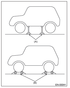
- Rigid rack
- Free roller
2. SUBARU SELECT MONITOR
1) Check that no DTC remains after clearing memory.
<Ref. to EN(H4SO)(diag)-51, Clear Memory Mode.>
2) Warm up the engine.
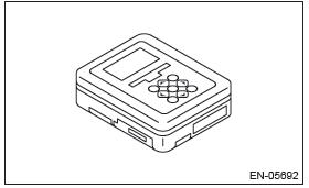
3) Prepare the Subaru Select Monitor kit. <Ref. to EN(H4SO)(diag)-8, PREPARATION TOOL, General Description.>
4) Prepare PC with Subaru Select Monitor installed.
5) Connect the USB cable to SDI (Subaru Diagnosis Interface) and USB port on the personal computer (dedicated port for the Subaru Select Monitor).
NOTE: The dedicated port for the Subaru Select Monitor means the USB port which was used to install the Subaru Select Monitor.
6) Connect the diagnosis cable to SDI.
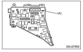
7) Install the delivery (test) mode fuse (A) of the fuse box.
CAUTION: Do not use any fuses that are installed on the vehicle.
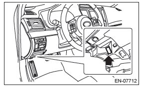
8) Connect SDI to data link connector located in the lower portion of the instrument panel (on the driver's side).
CAUTION: Do not connect the scan tools except for Subaru Select Monitor and general scan tool.
9) Start the PC.
10) Turn the ignition switch to ON (engine OFF) and run the "PC application for Subaru Select Monitor".
11) On "Main Menu" display, select {Each System Check}.
12) On "System Selection Menu" display, select {Engine Control System}.
13) Click the [OK] button after the information of engine type has been displayed.
14) On "Engine Diagnosis" display, select {Dealer Check Mode Procedure}.
15) When the "Perform Inspection (Dealer Check) Mode ?" is shown on the screen, click the [Next] button.
16) Perform subsequent procedures as instructed on the display screen.
- If trouble still remains in the memory, the corresponding DTC appears on the display screen.
NOTE:
- For detailed operation procedures, refer to "PC application help for Subaru Select Monitor".
- For details concerning DTC, refer to "List of Diagnostic Trouble Code (DTC)". <Ref. to EN(H4SO)(diag)-78, List of Diagnostic Trouble Code (DTC).>
- Release the parking brake.
- The speed difference between front and rear wheels may illuminate the ABS warning light, but this does not indicate a malfunction. When engine control system diagnosis is finished, perform the VDC memory clearance procedure of self-diagnosis function. <Ref. to VDC(diag)-25, Clear Memory Mode.>
3. GENERAL SCAN TOOL
1) Check that no DTC remains after clearing memory.
<Ref. to EN(H4SO)(diag)-31, MODE $04 (CLEAR/RESET EMISSION-RELATED DIAGNOSTIC INFORMATION), OPERATION, General Scan Tool.>
2) Warm up the engine.
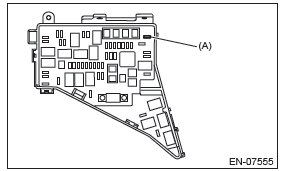
3) Install the delivery (test) mode fuse (A) of the main fuse box.
CAUTION: Do not use any fuses that are installed on the vehicle.
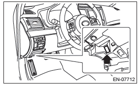
4) Connect the general scan tool to data link connector located in the lower portion of the instrument panel (on the driver's side).
CAUTION: Do not connect the scan tools except for Subaru Select Monitor and general scan tool.
5) Start the engine.
NOTE:
- Ensure the selector lever is placed in the "P" range before starting. (CVT model)
- Depress the clutch pedal when starting engine. (MT model)
6) Turn the neutral position switch to ON using select lever or shift lever.
7) Depress the brake pedal to turn the brake switch ON. (CVT model)
8) Keep the engine speed in 2,500 - 3,000 rpm range for 40 seconds.
9) Place the select lever or shift lever in "D" position (CVT model) or "1st gear" (MT model) and drive the vehicle at 5 to 10 km/h (3 to 6 MPH).
NOTE:
- For AWD model, release the parking brake.
- The speed difference between front and rear wheels may illuminate the ABS warning light, but this does not indicate a malfunction. When engine control system diagnosis is finished, perform the VDC memory clearance procedure of self-diagnosis function. <Ref. to VDC(diag)-25, Clear Memory Mode.>
10) Using the general scan tool, check for DTC and record the result(s).
NOTE:
- For detailed operation procedures, refer to the general scan tool operation manual.
- For details concerning DTC, refer to "List of Diagnostic
Trouble Code (DTC)".
<Ref. to EN(H4SO)(diag)-78, List of Diagnostic Trouble Code (DTC).>
READ NEXT:
 Drive Cycle
A: PROCEDURE
It is necessary to perform the drive cycle listed below if DTC is not found
in the Inspection Mode. It is possible
to complete diagnosis of the DTC by performing the indicated drive cycl
Malfunction Indicator Light
A: PROCEDURE
B: ACTIVATION OF MALFUNCTION
INDICATOR LIGHT
1) When the ignition switch is turned to ON (engine
OFF), the malfunction indicator light (A) in the combination
meter illuminates.
NOTE:
If
SEE MORE:
Low fuel warning light
The low fuel warning light illuminates when the tank is nearly empty approximately
2.6 US gal (10.0 liters, or 2.2 Imp gal). It only operates when the ignition switch
is in the “ON” position.
NOTE
This light does not turn off unless the tank is replenished up to an internal
fuel quanti
Brake assist system
WARNING
Do not be overconfident about the brake assist. It is not a system that brings
more braking ability to the vehicle beyond its braking capability. Always use the
utmost care when driving regarding vehicle speed and safe distance.
CAUTION
When you need to brake suddenly, continue depres
