
Subaru Outback (BR): Components
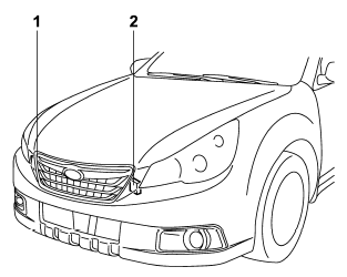
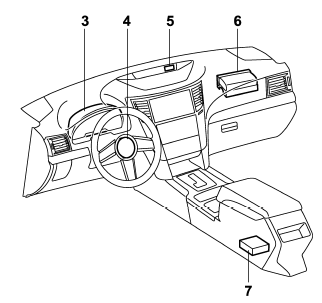
1) Front sub sensor (right-hand side) 2) Front sub sensor (left-hand side) 3) SRS airbag system warning light 4) Frontal airbag module (driver’s side) 5) Front passenger’s frontal airbag ON and OFF indicator 6) Frontal airbag module (front passenger’s side) 7) Airbag control module (including impact sensor [all models] and rollover sensor [Outback])
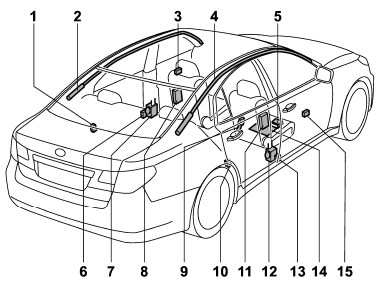
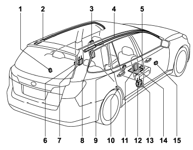
1) Rear wheel house impact sensor (lefthand side) 2) Curtain airbag module (left-hand side) 3) Front door impact sensor (left-hand side) 4) Curtain airbag module (right-hand side) 5) Front passenger’s occupant detection control module 6) Center pillar impact sensor (left-hand side) 7) Seatbelt pretensioner (left-hand side) 8) Side airbag module (left-hand side) 9) Seatbelt buckle switch (right-hand side) 10) Rear wheel house impact sensor (righthand side) 11) Side airbag module (right-hand side) 12) Seatbelt pretensioner (right-hand side) 13) Center pillar impact sensor (right-hand side) 14) Front passenger’s occupant detection system weight sensor 15) Front door impact sensor (right-hand side)
READ NEXT:
 SUBARU advanced frontal airbag system
Your vehicle is equipped with a SUBARU advanced frontal airbag system that complies
with the new advanced frontal airbag requirements in the amended Federal Motor Vehicle
Safety Standard (FMVSS) N
Front passenger’s SRS frontal airbag
The front passenger’s SRS frontal airbag uses a dual stage inflator. The inflator
operates in different ways depending on the severity of impact.
The total load on the seat is monitored by the pa
SEE MORE:
Wiper and Washer System
A: WIRING DIAGRAM
1. WIPER AND WASHER (FRONT)
Refer to "Front Wiper and Washer System" in the wiring diagram. <Ref. to
WI-169, WIRING DIAGRAM, Front
Wiper and Washer System.>
2. WIPER AND WASHER (REAR)
Refer to "Rear Wiper and Washer System" in the wiring diagram. <Ref. to
WI-219, WIRING
Heater and Cooling Unit
A: REMOVAL
1) Disconnect the ground cable from battery.
2) Using the refrigerant recovery system, discharge refrigerant. <Ref. to AC-24,
PROCEDURE, Refrigerant
Recovery Procedure.>
3) Drain the coolant from the radiator.
H4 non-turbo model: <Ref. to CO(H4SO)-14, DRAINING OF ENGINE COOL
