Subaru Outback (BR): DTC P0171, P0172, P0181, P0182, P0183, P0196, P0197, P0198, P0201, P0202, P0203, P0204, P0222, P0223, P0301, P0302, P0303, P0304
AR:DTC P0171 SYSTEM TOO LEAN (BANK 1)
1. OUTLINE OF DIAGNOSIS
Detect fuel system malfunction by the amount of main feedback control.
Diagnostic method
Fuel system is diagnosed by comparing the target air fuel ratio calculated by ECM with the actual air fuel ratio measured by sensor.
2. ENABLE CONDITION

Map 1

3. GENERAL DRIVING CYCLE
Perform the diagnosis continuously at idling or at a constant speed after warming up the engine.
4. DIAGNOSTIC METHOD
- Abnormality Judgment
Compare the diagnostic value (fsobd) with the threshold value, and if a condition meeting the malfunction criteria below continues for 10 s × 5 time(s) or more, judge that there is a fault in the fuel system.
Judgment Value
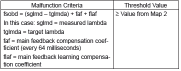
Map 2

Time Needed for Diagnosis: 10 s × 5 time(s)
Malfunction Indicator Light Illumination: Illuminates when malfunction occurs in 2 continuous driving cycles.
- Normality Judgment
Judge as OK and clear the NG if the continuous time while the following conditions are established is more than the predetermined time.
Judgment Value

Time Needed for Diagnosis: 10 s
AS:DTC P0172 SYSTEM TOO RICH (BANK 1)
1. OUTLINE OF DIAGNOSIS
Detect fuel system malfunction by the amount of main feedback control.
Diagnostic method
Fuel system is diagnosed by comparing the target air fuel ratio calculated by ECM with the actual air fuel ratio measured by sensor.
2. ENABLE CONDITION
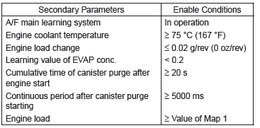
Map 1

3. GENERAL DRIVING CYCLE
Perform the diagnosis continuously at idling or at a constant speed after warming up the engine.
4. DIAGNOSTIC METHOD
- Abnormality Judgment
Compare the diagnostic value (fsobd) with the threshold value, and if a condition meeting the malfunction criteria below continues for 10 s × 5 time(s) or more, judge that there is a fault in the fuel system.
Judgment Value
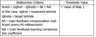
Map 2

Time Needed for Diagnosis: 10 s × 5 time(s)
Malfunction Indicator Light Illumination: Illuminates when malfunction occurs in 2 continuous driving cycles.
- Normality Judgment
Judge as OK if the status that the criteria below are met continues for 10 seconds.
Judgment Value

Time Needed for Diagnosis: 10 s
AT:DTC P0181 FUEL TEMPERATURE SENSOR "A" CIRCUIT RANGE/PERFORMANCE
1. OUTLINE OF DIAGNOSIS
Detect faults in the fuel temperature sensor output properties.
Diagnosis is performed in two methods (drift diagnosis and stuck diagnosis). If either is NG, judge as NG. If both are OK, Judge as OK and clear the NG.
Drift Diagnosis
Normally fuel temperature is lower than engine coolant temperature. When the fuel temperature becomes higher than the engine coolant temperature, the range is considered to be shifted, and judged as NG.
Stuck Diagnosis
As the engine warms up (cumulative amount of intake air after starting is large), if the fuel temperature which should rise does not, determine as being stuck and NG.
2. COMPONENT DESCRIPTION
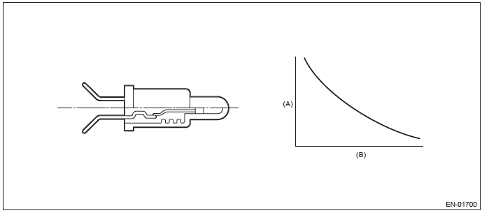
- Resistance value (Ω)
- Fuel temperature ºC (ºF)
3. ENABLE CONDITION
DRIFT DIAGNOSIS

4. GENERAL DRIVING CYCLE
Always perform the diagnosis continuously.
5. DIAGNOSTIC METHOD
- Abnormality Judgment
If the duration of time while the following conditions are met is longer than the time indicated, judge as NG.
Judgment Value
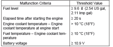
Time Needed for Diagnosis: 120 s
Malfunction Indicator Light Illumination: Illuminates when malfunction occurs in 2 continuous driving cycles.
- Normality Judgment
Judge as OK and clear the NG if the continuous time while the following conditions are established is more than the predetermined time.
Judgment Value
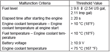
Time Needed for Diagnosis: Less than 1 second
6. ENABLE CONDITION
Stuck Diagnosis

7. GENERAL DRIVING CYCLE
Perform the diagnosis continuously 20 seconds after starting engine.
8. DIAGNOSTIC METHOD
- Abnormality Judgment
Judge as NG when the following conditions are established.
Judgment Value

Time Needed for Diagnosis: Less than 1 second
Malfunction Indicator Light Illumination: Illuminates when malfunction occurs in 2 continuous driving cycles.
- Normality Judgment
Judge as OK and clear the NG if the following conditions are established.
Judgment Value

Time Needed for Diagnosis: Less than 1 second
AU:DTC P0182 FUEL TEMPERATURE SENSOR "A" CIRCUIT LOW INPUT
1. OUTLINE OF DIAGNOSIS
Detect the open or short circuit of fuel temperature sensor.
Judge as NG if out of specification.
2. COMPONENT DESCRIPTION
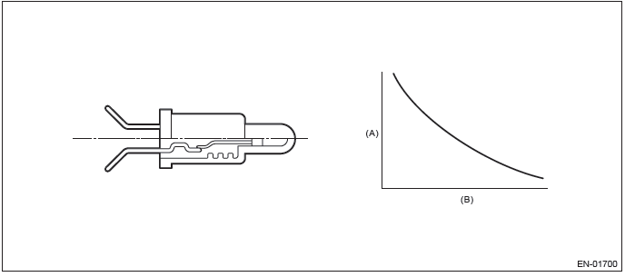
- Resistance value (Ω)
- Fuel temperature ºC (ºF)
3. ENABLE CONDITION

4. GENERAL DRIVING CYCLE
Always perform the diagnosis continuously.
5. DIAGNOSTIC METHOD
- Abnormality Judgment
If the duration of time while the following conditions are met is longer than the time indicated, judge as NG.
Judgment Value

Time Needed for Diagnosis: 2500 ms
Malfunction Indicator Light Illumination: Illuminates as soon as a malfunction occurs.
- Normality Judgment
Judge as OK and clear the NG if the continuous time while the following conditions are established is more than the predetermined time.
Judgment Value

Time Needed for Diagnosis: Less than 1 second
AV:DTC P0183 FUEL TEMPERATURE SENSOR "A" CIRCUIT HIGH INPUT
1. OUTLINE OF DIAGNOSIS
Detect the open or short circuit of fuel temperature sensor.
Judge as NG if out of specification.
2. COMPONENT DESCRIPTION
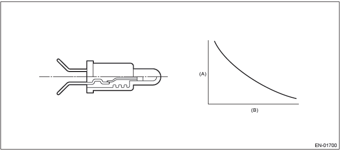
- Resistance value (Ω)
- Fuel temperature ºC (ºF)
3. ENABLE CONDITION

4. GENERAL DRIVING CYCLE
Always perform the diagnosis continuously.
5. DIAGNOSTIC METHOD
- Abnormality Judgment
If the duration of time while the following conditions are met is longer than the time indicated, judge as NG.
Judgment Value

Time Needed for Diagnosis: 2500 ms
Malfunction Indicator Light Illumination: Illuminates as soon as a malfunction occurs.
- Normality Judgment
Judge as OK and clear the NG if the continuous time while the following conditions are established is more than the predetermined time.
Judgment Value

Time Needed for Diagnosis: Less than 1 second
AW:DTC P0196 ENGINE OIL TEMPERATURE SENSOR CIRCUIT RANGE/PERFORMANCE
1. OUTLINE OF DIAGNOSIS
Detect for abnormal values in the oil temperature sensor output properties.
Judge as NG when the oil temperature does not rise even though the engine is running under a condition where it should rise.
2. ENABLE CONDITION

Map

3. GENERAL DRIVING CYCLE
Perform the diagnosis continuously after starting the engine.
4. DIAGNOSTIC METHOD
- Abnormality Judgment
Judge as NG when the following conditions are established.
Judgment Value

After engine start oil temperature sensor characteristic diagnosis timer (timer for diagnosis).
a. Timer stop at fuel cut
b. During the driving conditions except a) above, timer counts up as follows.
64 ms + TOILCNT ms (when at 64 ms)
Where, TOILCNT is determined as follows,
TOILCNT = 0 at idle switch ON
For TOILCNT at Idle switch off, refer to the following table.

After engine start oil temperature characteristic diagnosis timer judgment value (t).
t = 1882940 ms - 43302 ms × Ti (t ≥ 2400000)
Ti = The lowest coolant temperature after starting the engine.
Time Needed for Diagnosis: Less than 1 second
Malfunction Indicator Light Illumination: Illuminates when malfunction occurs in 2 continuous driving cycles.
- Normality Judgment
Judge as OK and clear the NG if the following conditions are established.
Judgment Value

Time Needed for Diagnosis: Less than 1 second
AX:DTC P0197 ENGINE OIL TEMPERATURE SENSOR LOW
1. OUTLINE OF DIAGNOSIS
Detect the open or short circuit of the oil temperature sensor.
Judge as NG when outside of the judgment value.
2. ENABLE CONDITION

3. GENERAL DRIVING CYCLE
Always perform the diagnosis continuously.
4. DIAGNOSTIC METHOD
- Abnormality Judgment
If the duration of time while the following conditions are met is longer than the time indicated, judge as NG.
Judgment Value

Time Needed for Diagnosis: 500 ms
Malfunction Indicator Light Illumination: Illuminates as soon as a malfunction occurs.
- Normality Judgment
Judge as OK and clear the NG if the continuous time while the following conditions are established is more than the predetermined time.
Judgment Value

Time Needed for Diagnosis: Less than 1 second
AY:DTC P0198 ENGINE OIL TEMPERATURE SENSOR HIGH
1. OUTLINE OF DIAGNOSIS
Detect the open or short circuit of the oil temperature sensor.
Judge as NG when outside of the judgment value.
2. ENABLE CONDITION

3. GENERAL DRIVING CYCLE
Always perform the diagnosis continuously.
4. DIAGNOSTIC METHOD
- Abnormality Judgment
If the duration of time while the following conditions are met is longer than the time indicated, judge as NG.
Judgment Value

Time Needed for Diagnosis: 500 ms
Malfunction Indicator Light Illumination: Illuminates as soon as a malfunction occurs.
- Normality Judgment
Judge as OK and clear the NG if the continuous time while the following conditions are established is more than the predetermined time.
Judgment Value

Time Needed for Diagnosis: Less than 1 second
AZ:DTC P0201 INJECTOR #1
1. OUTLINE OF DIAGNOSIS
Based on the self-diagnostic result of the injector driving IC, judge the injector driving circuit as normal or abnormal.
Injector driving IC detects the status of "fuel remains injected" or "fuel is not injected" as a malfunction.
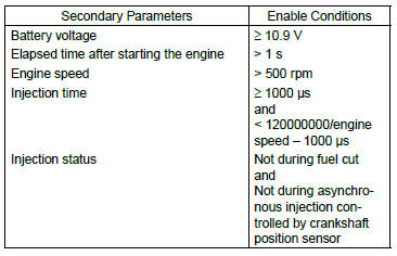
2. ENABLE CONDITIONS
3. GENERAL DRIVING CYCLE
Always perform the diagnosis continuously.
4. DIAGNOSTIC METHOD
- Abnormality Judgment
Judge as NG when the following conditions are established.
Judgment Value

Time Needed for Diagnosis: 2500 ms
Malfunction Indicator Light Illumination: Illuminates as soon as a malfunction occurs.
- Normality Judgment
Judge as OK and clear the NG if the following conditions are established.
Judgment Value

Time Needed for Diagnosis: Less than 1 second
BA:DTC P0202 INJECTOR #2
1. OUTLINE OF DIAGNOSIS
NOTE: For the detection standard, refer to DTC P0201. <Ref. to GD(H4SO)-105, DTC P0201 INJECTOR #1, Diagnostic Trouble Code (DTC) Detecting Criteria.>
BB:DTC P0203 INJECTOR #3
1. OUTLINE OF DIAGNOSIS
NOTE: For the detection standard, refer to DTC P0201. <Ref. to GD(H4SO)-105, DTC P0201 INJECTOR #1, Diagnostic Trouble Code (DTC) Detecting Criteria.>
BC:DTC P0204 INJECTOR #4
1. OUTLINE OF DIAGNOSIS
NOTE: For the detection standard, refer to DTC P0201. <Ref. to GD(H4SO)-105, DTC P0201 INJECTOR #1, Diagnostic Trouble Code (DTC) Detecting Criteria.>
BD:DTC P0222 THROTTLE/PEDAL POSITION SENSOR/SWITCH "B" CIRCUIT LOW
1. OUTLINE OF DIAGNOSIS
Detect the open or short circuit of throttle position sensor 2.
Judge as NG if out of specification.
2. COMPONENT DESCRIPTION
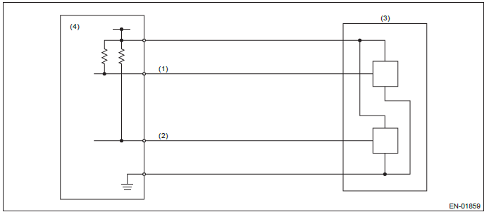
- Throttle position sensor 1 signal
- Throttle position sensor 2 signal
- Throttle position sensor
- Engine control module (ECM)
3. ENABLE CONDITION

4. GENERAL DRIVING CYCLE
Always perform the diagnosis continuously.
5. DIAGNOSTIC METHOD
- Abnormality Judgment
If the duration of time while the following conditions are met is longer than the time indicated, judge as NG.
Judgment Value

Time Needed for Diagnosis: 24 ms
Malfunction Indicator Light Illumination: Illuminates as soon as a malfunction occurs.
- Normality Judgment
Judge as OK and clear the NG if the continuous time while the following conditions are established is more than the predetermined time.
Judgment Value

Time Needed for Diagnosis: 24 ms
BE:DTC P0223 THROTTLE/PEDAL POSITION SENSOR/SWITCH "B" CIRCUIT HIGH
1. OUTLINE OF DIAGNOSIS
Detect the open or short circuit of throttle position sensor 2.
Judge as NG if out of specification.
2. COMPONENT DESCRIPTION
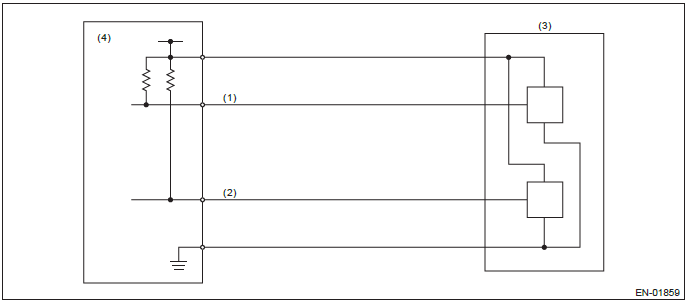
- Throttle position sensor 1 signal
- Throttle position sensor 2 signal
- Throttle position sensor
- Engine control module (ECM)
3. ENABLE CONDITION

4. GENERAL DRIVING CYCLE
Always perform the diagnosis continuously.
5. DIAGNOSTIC METHOD
- Abnormality Judgment
If the duration of time while the following conditions are met is longer than the time indicated, judge as NG.
Judgment Value

Time Needed for Diagnosis: 24 ms
Malfunction Indicator Light Illumination: Illuminates as soon as a malfunction occurs.
- Normality Judgment
Judge as OK and clear the NG if the continuous time while the following conditions are established is more than the predetermined time.
Judgment Value

Time Needed for Diagnosis: 24 ms
BF:DTC P0301 CYLINDER 1 MISFIRE DETECTED
1. OUTLINE OF DIAGNOSIS
Detect the presence of misfire occurrence. (Revolution fluctuation method)
Monitoring Misfire which influences exhaust deterioration (1.5 times of FTP) and catalyst damage is made obligatory by the law. Misfire affecting these two has two patterns below. :
- Intermittent misfire (The same cylinder misfires in random, or different cylinders misfire in random.): FTP 1.5 times misfire
- Every time misfire (The same cylinder misfires every time.): FTP 1.5 times misfire, Catalyst damage misfire
The following detecting methods are adopted for these detection.
1) Intermittent misfire: FTP 1.5 times misfire
- 180º Interval Difference Method (MT: 1,800 rpm or less; CVT: None)
- 360º Interval Difference Method (whole range)
- 720º Interval Difference Method (3,000 rpm or more)
2) Misfire every time: FTP 1.5 times misfire, Catalyst damage misfire
- 360º Interval Difference Method
2. ENABLE CONDITION
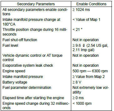
Map 1
- CVT model

- MT model

Map 2 (PZEV CVT model)
- Normal ignition
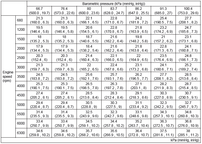
- Idling ignition
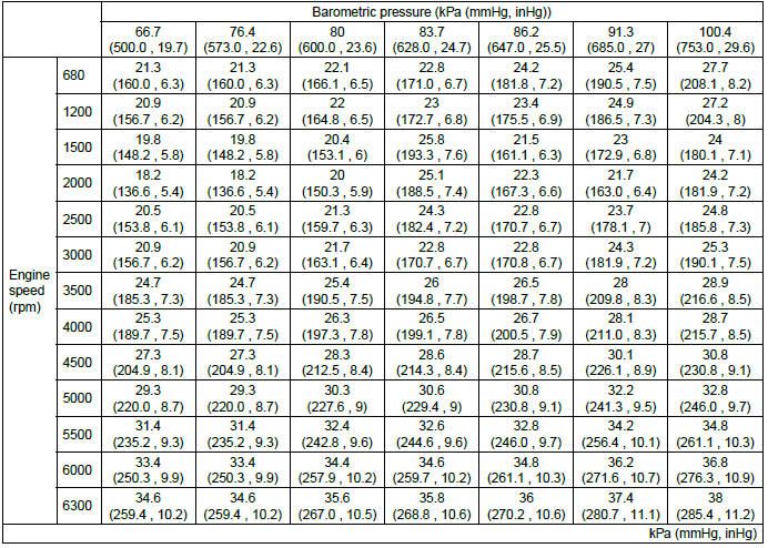
Map 2 (PZEV MT model)
- Normal ignition
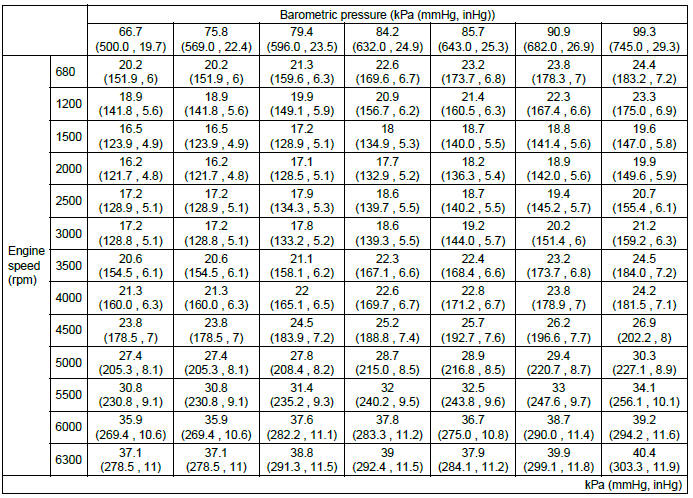
- Idling ignition
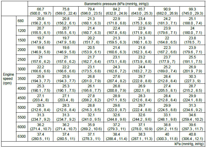
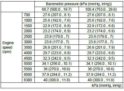
Map 2 (CVT model except for PZEV)
- Normal ignition
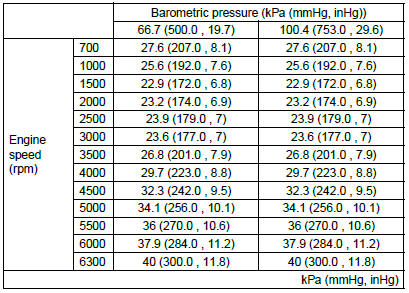
- Idling ignition
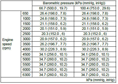
Map 2 (MT model except for PZEV)
- Normal ignition
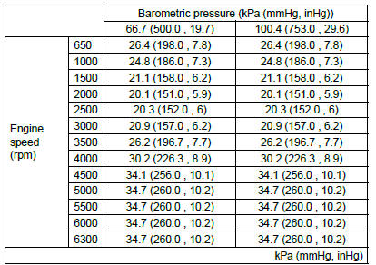
- Idling ignition
3. GENERAL DRIVING CYCLE
- If conditions are met, it is possible to detect the misfires from idling to high engine speed. However, to avoid excessive load or harm to the engine, perform diagnosis at idle.
- Perform the diagnosis continuously.
4. DIAGNOSTIC METHOD
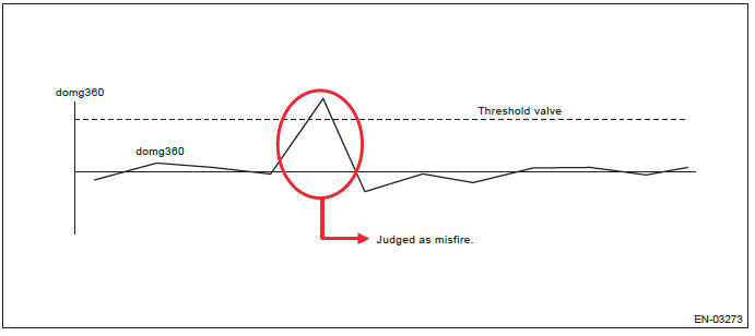
When a misfire occurs, the engine speed will decrease and the crankshaft position speed will change. Calculate the interval difference value (diagnostic value) from crankshaft position speed by the following formula, and judge whether a misfire is occurring or not comparing the calculated result with judgment value. Count the number of misfires, if the misfire ratio is higher during 1000 revs. or 200 revs., judge corresponding cylinders as NG.

As shown in the following figure, pick a cylinder as the standard and name it omg 0. And the former crankshaft position speed is named omg 1, the second former crankshaft position speed is named omg 2, the third is named omg 3, etc.
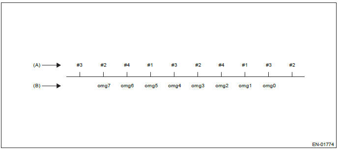
- Ignition order
- Crankshaft position speed
180º Interval Difference Method

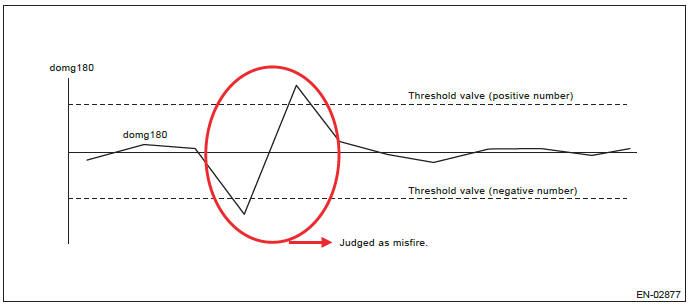
360º Interval Difference Method

720º Interval Difference Method

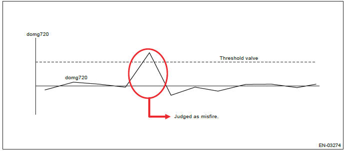
- FTP 1.5 times misfire (Misfire occurrence level which influences exhaust gas)
- Abnormality Judgment
Judgment Value (Judge that malfunction occurs when the misfire ratio is high in 1000 engine revs.)

Time Needed for Diagnosis: 1000 engine revs.
Malfunction Indicator Light Illumination: Illuminates when malfunction occurs in 2 continuous driving cycles.
- Normality Judgment
Judgment Value

Time Needed for Diagnosis: 1000 engine revs.
- Catalyst damage misfire (Misfire occurrence level damaging catalyst)
- Abnormality Judgment
Judgment Value

Map 3
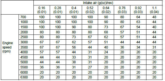
Time Needed for Diagnosis: 200 engine revs.
Malfunction Indicator Light Illumination: Illuminates as soon as a malfunction occurs.
- Normality Judgment
Judgment Value

Time Needed for Diagnosis: 200 engine revs.
BG:DTC P0302 CYLINDER 2 MISFIRE DETECTED
1. OUTLINE OF DIAGNOSIS
NOTE: For the detection standard, refer to DTC P0301. <Ref. to GD(H4SO)-111, DTC P0301 CYLINDER 1 MISFIRE DETECTED, Diagnostic Trouble Code (DTC) Detecting Criteria.>
BH:DTC P0303 CYLINDER 3 MISFIRE DETECTED
1. OUTLINE OF DIAGNOSIS
NOTE: For the detection standard, refer to DTC P0301. <Ref. to GD(H4SO)-111, DTC P0301 CYLINDER 1 MISFIRE DETECTED, Diagnostic Trouble Code (DTC) Detecting Criteria.>
BI: DTC P0304 CYLINDER 4 MISFIRE DETECTED
1. OUTLINE OF DIAGNOSIS
NOTE: For the detection standard, refer to DTC P0301. <Ref. to GD(H4SO)-111, DTC P0301 CYLINDER 1 MISFIRE DETECTED, Diagnostic Trouble Code (DTC) Detecting Criteria.>

