Subaru Outback (BR): DTC P0442, P0447, P0448, P0451, P0452, P0453, P0456, P0457, P0458, P0459, P0461, P0462, P0463, P0464
BV:DTC P0442 EVAPORATIVE EMISSION CONTROL SYSTEM LEAK DETECTED (SMALL LEAK)
1. OUTLINE OF DIAGNOSIS
The evaporative system monitor detects leak up to 0.020 inch in the fuel tank and evaporative emissions system.
If the fuel cap is not present or has not been correctly tightened after a refueling event, a malfunction is also detected. These malfunctions are detected by monitoring the fuel tank and system pressure during an intrusive pull-down pressure test. Pull down is accomplished via the purge valve while the engine is running.
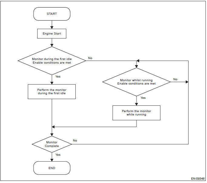
Monitors run during the first idle after engine start and while driving.
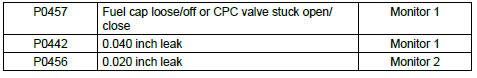
The diagnostic is classified into two monitors. The first monitor detects a 0.040 inch leak, fuel cap loose/off, and canister purge valve stuck open/close whilst the other monitor detects a 0.020 inch leak when the vehicle is moving or during the first idle. Failures, DTCs and monitor methods are as follows.
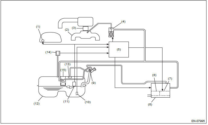
- Fuel gauge
- Intake manifold
- Throttle body
- Purge control solenoid valve (CPC valve)
- Engine control module (ECM)
- Canister
- Drain valve (CCV)
- Drain filter
- Shut-off valve
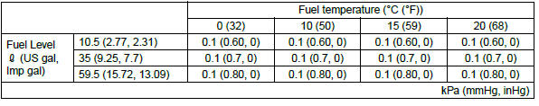
- Fuel temperature sensor
- Fuel level sensor
- Fuel tank
- Fuel cut valve
- Fuel tank pressure sensor
- Vent valve
Monitor 1
- P0457 Fuel cap loose/off or CPC valve stuck open/close
- P0442 0.040 inch leak check
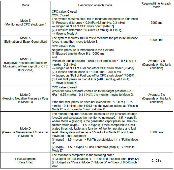
This monitor detects CPC valve stuck open/close, fuel cap loose/off, and 0.040 inch leak in the evaporative emission system by monitoring the fuel tank system pressure an intrusive pull-down pressure test. The monitor consists of Modes Z, A, B, C and D. There are three judgment times for these malfunctions. CPC valve stuck open is performed in Mode Z, CPC valve stuck closed or fuel cap loose/off is in Mode B, 0.040 inch leak is in Mode D.
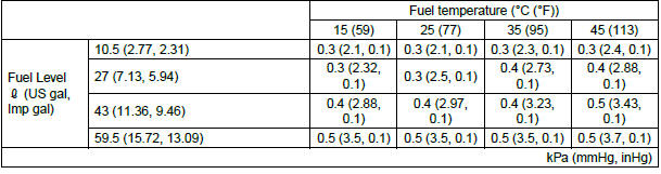
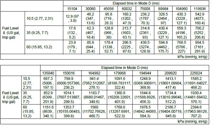
Map 1 (Threshold value for 0.040 inch leak)
Monitor 2
P0456 0.020 inch leak check
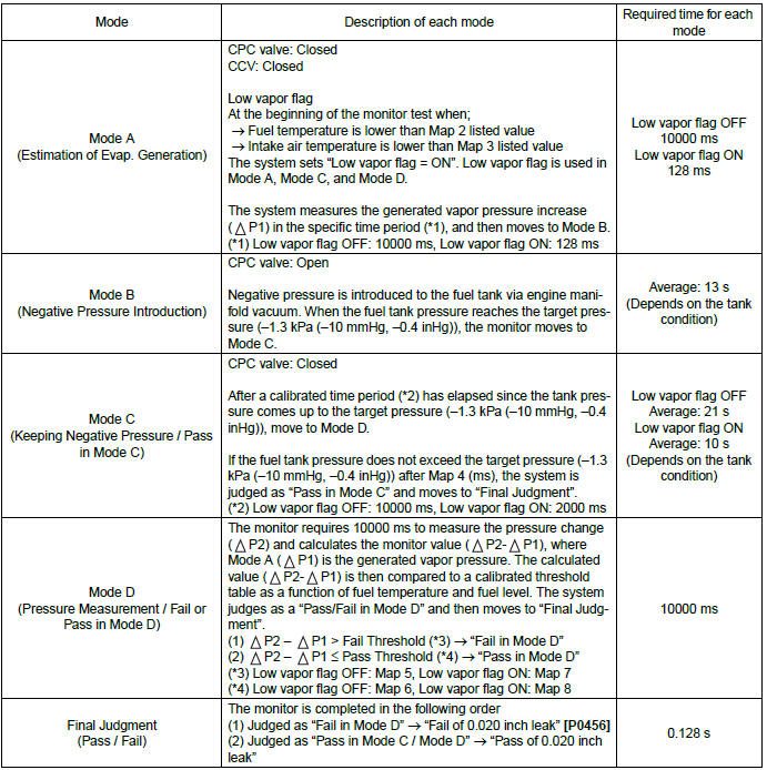
This monitor detects a very small leak (0.020 inch) in the evaporative emissions system by monitoring the fuel tank and system pressure during an intrusive pull-down pressure test. Pull down is accomplished via the purge valve while the engine is running. The monitor runs during the first idle after engine start and also while the vehicle is running.
Monitor 2 (first idle condition)
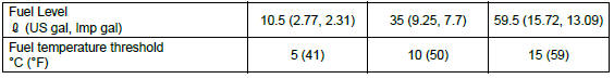
Map 2 (Fuel temperature threshold for "Low vapor flag")
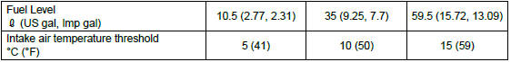
Map 3 (intake air temperature threshold for "Low Vapor Flag")
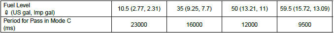
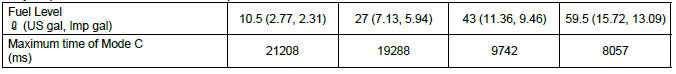
Map 4 (Period for judgment of Pass in Mode C)
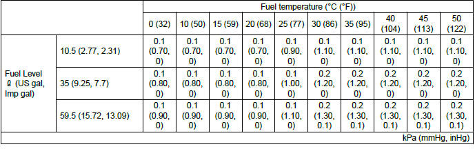
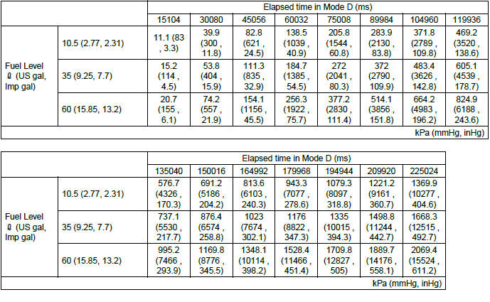
Map 5 (Threshold value for 0.020 inch leak in Mode D under normal condition)
Map 6 (Threshold value for Pass in Mode D under normal conditions)
Map 7 (Threshold value for 0.020 inch leak in Mode D with under low vapor conditions)
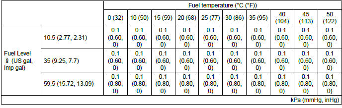
Map 8 (Threshold value for Pass in Mode D with under low vapor conditions)
Monitor 2 (vehicle running condition)
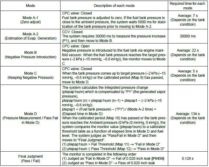
Map 9 (Maximum time of Mode C)
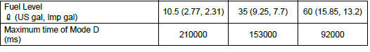
Map 10 (Maximum time of Mode D)
Map 11 (Threshold value for 0.020 inch leak in Mode D)
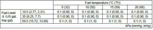
Map 12 (Threshold value for Pass in Mode D)
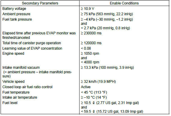
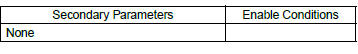
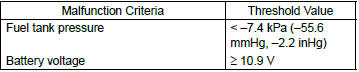
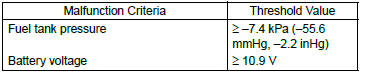
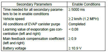
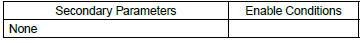
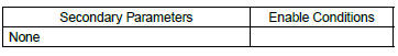
2. ENABLE CONDITION
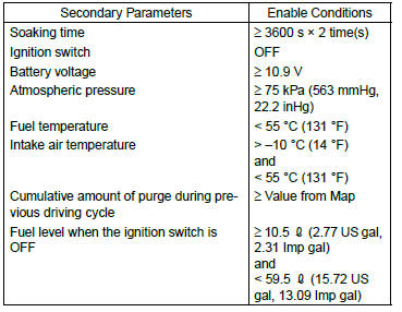
Monitor 1
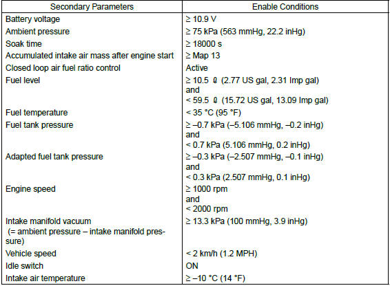
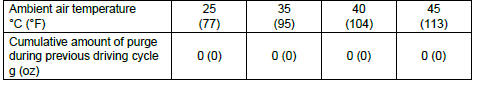
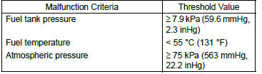
Monitor 2 (first idle condition)
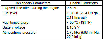
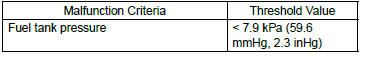
Monitor 2 (vehicle running condition)

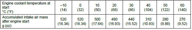
Map 13 (Accumulated intake air mass after engine start)
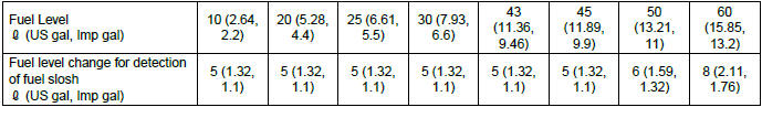
Map 14 (Threshold value the fuel slosh detection)
3. GENERAL DRIVING CYCLE
Monitor 1
Perform the diagnosis when the cumulative time of canister purge after engine start becomes 120 seconds or more, at a vehicle speed of 32 km/h (20 MPH) or more.
If judgment cannot be made, repeat the diagnosis after a predetermined interval has passed.
Monitor 2 (first idle condition)
Perform the diagnosis only once at the fast idle (the idling before starting to move) after soaking of 5 hours or more, in conditions that A/F feedback has been executed and catalytic converter has been warmed up (approx. 25 seconds after engine start).
If judgment cannot be made, or the diagnosis cannot be performed at fast idle, do not repeat the diagnosis in this driving cycle.
Monitor 2 (vehicle running condition)
Perform this procedure only when the diagnosis cannot be completed at fast idle.
Perform the diagnosis when the cumulative time of canister purge after engine start becomes 120 seconds or more, at a vehicle speed of 30 km/h (18.6 MPH) or more.
If judgment cannot be made, repeat the diagnosis after a predetermined interval has passed.
4. DIAGNOSTIC METHOD
- Monitor 1
- CPC valve stuck open
At the beginning of the Monitor 1, system performs CPC valve stuck open monitor in Mode Z. CPC valve and CCV are closed and the fuel tank pressure is monitored. The pressure transition over a calibrated time is then used to determine if the CPC valve is stuck open.
CPC valve stuck open test at Mode Z of Monitor 1
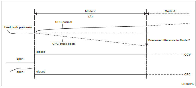
- 3000 ms
Judgment
- Pressure difference in Mode Z < 0.9 kPa (6.5 mmHg, 0.3 inHg) → Fail [CPC valve stuck open]: P0457
- Pressure difference in Mode Z ≥ 0.4 kPa (3 mmHg, 0.1 inHg) → Pass → move to Mode A
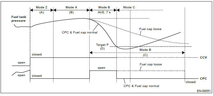
Fuel cap loose/off and CPC valve stuck close
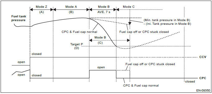
Fuel cap loose/off and CPC valve stuck close monitor is performed in Mode B of Monitor 1. The engine lowers the fuel tank pressure using intake manifold vacuum via the operation of the CPC valve. The pressure transition over a calibrated time is then used to determine if the Fuel cap loose/off or CPC valve stuck closed.
Fuel cap off or CPC stuck close at Mode B of Monitor 1
- 3000 ms
- 10000 ms
- 10000 ms
- -1.4 kPa (-10.5 mmHg, -0.4 inHg)
Judgment
- Elapsed time in Mode B ≥ 10000 ms and (Minimum tank pressure in Mode B) - (Initial tank pressure in Mode B) > -0.5 kPa (-4 mmHg, -0.2 inHg) → Fail [Fuel cap off or CPC valve stuck close]: P0457
- Fuel tank pressure ≤ -1.4 kPa (-10.5 mmHg, -0.4 inHg) → Pass → move to Mode C
Fuel cap loose at Mode B of Monitor 1
- 3000 ms
- 10000 ms
- 10000 ms + 25000 ms
- -1.4 kPa (-10.5 mmHg, -0.4 inHg)
Judgment
- Elapsed time in Mode B ≥ 10000 ms + 25000 ms → Fail [Fuel cap loose]: P0457
- Fuel tank pressure ≤ -1.4 kPa (-10.5 mmHg, -0.4 inHg) → Pass → move to Mode C
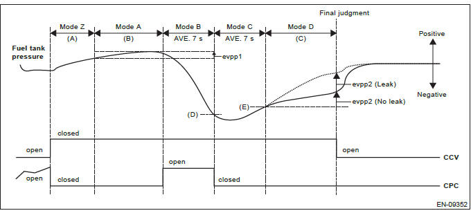
0.040 inch leak check
0.040 inch evaporative leak monitor is executed through Mode A to Mode D of Monitor 1. The engine lowers the fuel tank pressure using intake manifold vacuum via the canister purge operation during engine running.
Once the tank pressure reaches a calibrated target (below atmospheric pressure) the purge valve is closed and the fuel tank pressure is monitored. The pressure transition over a calibrated time period is then used to determine if the fuel tank system has a leak.
0.040 inch EVAP monitor test
- 3000 ms
- 10000 ms
- 10000 ms
- -1.4 kPa (-10.5 mmHg, -0.4 inHg)
- -1.3 kPa (-9.75 mmHg, -0.4 inHg)
Judgment
- evpp2 - 1.5 × evpp1 > Map 1 → Fail [0.040 inch Leak]: P0442
- evpp2 - 1.5 × evpp1 ≤ Map 1 → Pass [No Leak]
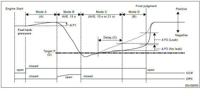
Monitor 2 (first idle condition)
0.020 inch leak check at first idle condition
An intrusive evaporative leak monitor test is run following the first engine start after a calibrated engine off soak period. The engine lowers the fuel tank pressure using intake manifold vacuum via the purge valve operation during engine idle. Once the tank pressure reaches a calibrated target (below atmospheric pressure) the purge valve is closed and the fuel tank pressure is monitored. The pressure transition over a calibrated time period is then used to determine if the fuel tank system has a leak.
Intrusive EVAP Monitor test at first Idle
- 128 ms or 10000 ms
- 10000 ms
- 2000 ms or 10000 ms
- -1.3 kPa (-10 mmHg, -0.4 inHg)
Judgment
 P2 -
P2 -
 P1 > Map 5 or Map 7 → Fail [0.020 inch Leak]: P0456
 P2 -
P2 -
 P1 ≤ Map 6 or Map 8 → Pass [No Leak]
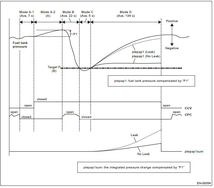
Monitor 2 (vehicle running condition)
0.020 inch Monitor during Vehicle Running (moving) Conditions
While the vehicle is vehicle running, the diagnostic intrusively pulls-down the fuel tank pressure using manifold vacuum via the purge valve. Once the tank pressure reaches a calibrated target (below atmospheric pressure) the purge valve is closed and the fuel tank pressure is monitored. The pressure transition over a calibrated time period is then used to determine if the fuel tank system has a leak.
Intrusive EVAP Monitor Test (Vehicle Running)
- 30000 ms
- -2 kPa (-15 mmHg, -0.6 inHg)
Judgment
- ptepap1sum > Map 11 → Fail [0.020 inch Leak]: P0456
- ptepap1sum ≤ Map 12 → Pass [No Leak]
BW:DTC P0447 EVAPORATIVE EMISSION CONTROL SYSTEM VENT CONTROL CIRCUIT OPEN
1. OUTLINE OF DIAGNOSIS
Detect open or short circuit of the drain valve.
Judge as NG when the ECM output level differs from the actual terminal level.
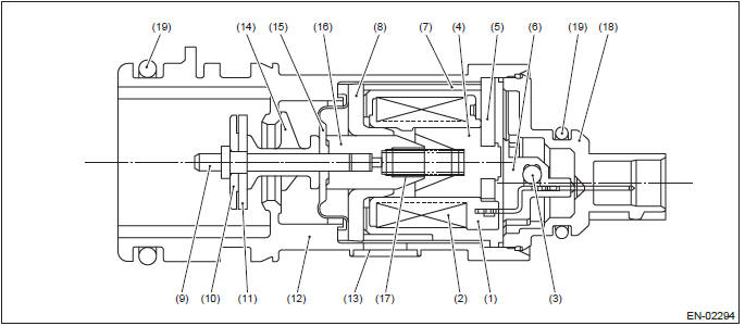
2. COMPONENT DESCRIPTION
- Bobbin
- Coil
- Diode
- Stator core
- End plate
- Body
- Yoke
- Magnetic plate
- Shaft
- Plate
- Valve
- Housing
- Filter
- Retainer
- Diaphragm
- Movable core
- Spring
- Cover
- O-ring
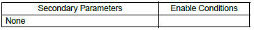
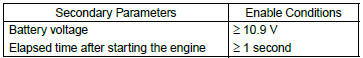
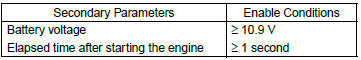
3. ENABLE CONDITION
4. GENERAL DRIVING CYCLE
Always perform the diagnosis continuously.
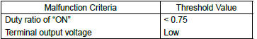
5. DIAGNOSTIC METHOD
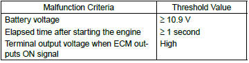
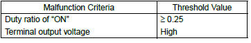
- Abnormality Judgment
If the duration of time while the following conditions are met is longer than the time indicated, judge as NG.
Judgment Value
Time Needed for Diagnosis: 2500 ms
Malfunction Indicator Light Illumination: Illuminates as soon as a malfunction occurs.
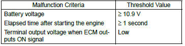
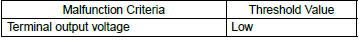
- Normality Judgment
Judge as OK and clear the NG if the continuous time while the following conditions are established is more than the predetermined time.
Judgment Value
Time Needed for Diagnosis: Less than 1 second
BX:DTC P0448 EVAPORATIVE EMISSION CONTROL SYSTEM VENT CONTROL CIRCUIT SHORTED
1. OUTLINE OF DIAGNOSIS
Detect open or short circuit of the drain valve.
Judge as NG when the ECM output level differs from the actual terminal level.
2. COMPONENT DESCRIPTION
- Bobbin
- Coil
- Diode
- Stator core
- End plate
- Body
- Yoke
- Magnetic plate
- Shaft
- Plate
- Valve
- Housing
- Filter
- Retainer
- Diaphragm
- Movable core
- Spring
- Cover
- O-ring
3. ENABLE CONDITION
4. GENERAL DRIVING CYCLE
Always perform the diagnosis continuously.
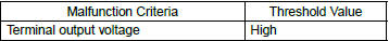
5. DIAGNOSTIC METHOD
- Abnormality Judgment
If the duration of time while the following conditions are met is longer than the time indicated, judge as NG.
Judgment Value
Time Needed for Diagnosis: 2500 ms
Malfunction Indicator Light Illumination: Illuminates as soon as a malfunction occurs.
- Normality Judgment
Judge as OK and clear the NG if the continuous time while the following conditions are established is more than the predetermined time.
Judgment Value
Time Needed for Diagnosis: Less than 1 second
BY:DTC P0451 EVAPORATIVE EMISSION CONTROL SYSTEM PRESSURE SENSOR
1. OUTLINE OF DIAGNOSIS
Detect malfunctions of tank pressure sensor output property by the following two diagnoses.
- DRIFT DIAGNOSIS
To detect drift malfunction and offset malfunction of tank pressure sensor, activate ECM in the predetermined soaking time after turning the ignition switch OFF, and check that the tank pressure sensor input value is equivalent to the barometric pressure.
For vehicles equipped with pressure control valve, be sure to open the pressure control valve when performing the diagnosis, because the pressure inside the tank increases if the ambient temperature rises during soaking.
- Stuck Diagnosis
When there is no pressure variation, which should have occurred in the tank considering the operation status, judge as NG.
2. COMPONENT DESCRIPTION
- Output voltage
- Input voltage
- To fuel tank
- Connector
- Terminals
3. ENABLE CONDITION
<DRIFT DIAGNOSIS>
Map
<Stuck Diagnosis>
4. GENERAL DRIVING CYCLE
<DRIFT DIAGNOSIS>
Perform the diagnosis only once when 3600 s × 2 time(s) has passed after the ignition switch is OFF.
<Stuck Diagnosis>
- Perform the diagnosis continuously after 60 s have passed since the engine started.
- Pay attention to the fuel level and temperature.
5. DIAGNOSTIC METHOD
<DRIFT DIAGNOSIS>
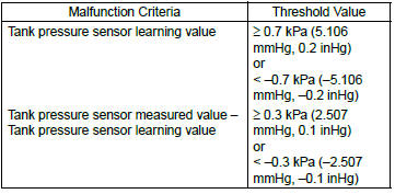
Abnormality Judgment
Judge as NG when one of the following conditions is established.
Judgment Value
Time Needed for Diagnosis: 10 seconds
Malfunction Indicator Light Illumination: Illuminates when malfunction occurs in 2 continuous driving cycles.
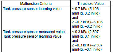
Normality Judgment
Judge as OK and clear the NG if the following conditions are established.
Judgment Value
Time Needed for Diagnosis: 10 seconds
<Stuck Diagnosis>
Abnormality Judgment
If the duration of time while the following conditions are met is longer than the time indicated, judge as NG.
Judgment Value
If the difference between the Max. fuel level every 60 s and Min. fuel level
every 60 s is less than 2  (0.53
US gal, 0.44 Imp gal), extend 60 s and make judgment with the Max. and Min.
values for the fuel level in 60
s × 2. If there is no difference after the extension of 60 s, extend the time
(60 s × 3, 60 s × 4, 60 s × 5) and
continue the judgment. If the difference between the Max. fuel level every 60 s
and Min. fuel level every 60
s is 2
(0.53
US gal, 0.44 Imp gal), extend 60 s and make judgment with the Max. and Min.
values for the fuel level in 60
s × 2. If there is no difference after the extension of 60 s, extend the time
(60 s × 3, 60 s × 4, 60 s × 5) and
continue the judgment. If the difference between the Max. fuel level every 60 s
and Min. fuel level every 60
s is 2  (0.53 US gal, 0.44
Imp gal) or more, the diagnosis counter counts up.
(0.53 US gal, 0.44
Imp gal) or more, the diagnosis counter counts up.
Time Needed for Diagnosis: 60 s × 16 time(s) or more
Malfunction Indicator Light Illumination: Illuminates when malfunction occurs in 2 continuous driving cycles.
Normality Judgment
Judge as OK and clear the NG if the continuous time while the following conditions are established is more than the predetermined time.
Judgment Value
Time Needed for Diagnosis: Less than 1 second
BZ:DTC P0452 EVAPORATIVE EMISSION CONTROL SYSTEM PRESSURE SENSOR LOW INPUT
1. OUTLINE OF DIAGNOSIS
Detect the open or short circuit of the fuel tank pressure sensor.
Judge as NG if out of specification.
2. COMPONENT DESCRIPTION
- Output voltage
- Input voltage
- To fuel tank
- Connector
- Terminals
3. ENABLE CONDITION
4. GENERAL DRIVING CYCLE
Always perform the diagnosis continuously.
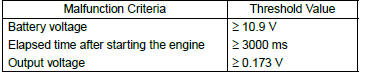
5. DIAGNOSTIC METHOD
- Abnormality Judgment
If the duration of time while the following conditions are met is longer than the time indicated, judge as NG.
Judgment Value
Time Needed for Diagnosis: 15000 ms
Malfunction Indicator Light Illumination: Illuminates as soon as a malfunction occurs.
- Normality Judgment
Judge as OK and clear the Judgment ValueNG if the continuous time while the following conditions are established is more than the predetermined time.
Judgment Value
Time Needed for Diagnosis: Less than 1 second
CA:DTC P0453 EVAPORATIVE EMISSION CONTROL SYSTEM PRESSURE SENSOR HIGH INPUT
1. OUTLINE OF DIAGNOSIS
Detect the open or short circuit of the fuel tank pressure sensor.
Judge as NG if out of specification.
2. COMPONENT DESCRIPTION
- Output voltage
- Input voltage
- To fuel tank
- Connector
- Terminals
3. ENABLE CONDITION
4. GENERAL DRIVING CYCLE
Perform the diagnosis when purging enable conditions are met without idling.
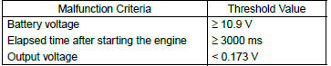
5. DIAGNOSTIC METHOD
- Abnormality Judgment
If the duration of time while the following conditions are met is longer than the time indicated, judge as NG.
Judgment Value
Time Needed for Diagnosis: 15000 ms
Malfunction Indicator Light Illumination: Illuminates as soon as a malfunction occurs.
- Normality Judgment
Judge as OK and clear the NG if the continuous time while the following conditions are established is more than the predetermined time.
Judgment Value
Time Needed for Diagnosis: Less than 1 second
CB:DTC P0456 EVAPORATIVE EMISSION CONTROL SYSTEM LEAK DETECTED (VERY SMALL LEAK)
1. OUTLINE OF DIAGNOSIS
NOTE: For the detection standard, refer to DTC P0442. <Ref. to GD(H4SO)-141, DTC P0442 EVAPORATIVE EMISSION CONTROL SYSTEM LEAK DETECTED (SMALL LEAK), Diagnostic Trouble Code (DTC) Detecting Criteria.>
CC:DTC P0457 EVAPORATIVE EMISSION CONTROL SYSTEM LEAK DETECTED (FUEL CAP LOOSE/OFF)
1. OUTLINE OF DIAGNOSIS
NOTE: For the detection standard, refer to DTC P0442. <Ref. to GD(H4SO)-141, DTC P0442 EVAPORATIVE EMISSION CONTROL SYSTEM LEAK DETECTED (SMALL LEAK), Diagnostic Trouble Code (DTC) Detecting Criteria.>
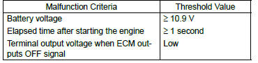
CD:DTC P0458 EVAPORATIVE EMISSION SYSTEM PURGE CONTROL VALVE CIRCUIT LOW
1. OUTLINE OF DIAGNOSIS
Detect open or short circuit of the purge control solenoid valve.
Judge as NG when the ECM output level differs from the actual terminal level.
2. COMPONENT DESCRIPTION
- To canister
- To intake manifold
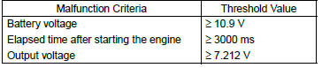
3. ENABLE CONDITION
4. GENERAL DRIVING CYCLE
Always perform the diagnosis after starting the engine.
5. DIAGNOSTIC METHOD
- Abnormality Judgment
If the duration of time while the following conditions are met is longer than the time indicated, judge as NG.
Judgment Value
Time Needed for Diagnosis: 2500 ms
Malfunction Indicator Light Illumination: Illuminates when malfunction occurs in 2 continuous driving cycles.
- Normality Judgment
Judge as OK and clear the NG if the continuous time while the following conditions are established is more than the predetermined time.
Judgment Value
Time Needed for Diagnosis: Less than 1 second
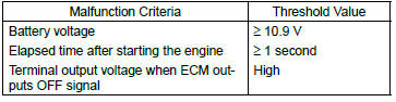
CE:DTC P0459 EVAPORATIVE EMISSION SYSTEM PURGE CONTROL VALVE CIRCUIT HIGH
1. OUTLINE OF DIAGNOSIS
Detect open or short circuit of the purge control solenoid valve.
Judge as NG when the ECM output level differs from the actual terminal level.
2. COMPONENT DESCRIPTION
- To canister
- To intake manifold
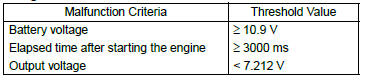
3. ENABLE CONDITION
4. GENERAL DRIVING CYCLE
Always perform the diagnosis after starting the engine.
5. DIAGNOSTIC METHOD
- Abnormality Judgment
If the duration of time while the following conditions are met is longer than the time indicated, judge as NG.
Judgment Value
Time Needed for Diagnosis: 2500 ms
Malfunction Indicator Light Illumination: Illuminates when malfunction occurs in 2 continuous driving cycles.
- Normality Judgment
Judge as OK and clear the NG if the continuous time while the following conditions are established is more than the predetermined time.
Judgment Value
Time Needed for Diagnosis: Less than 1 second
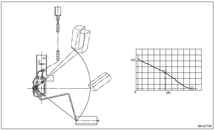
CF:DTC P0461 FUEL LEVEL SENSOR "A" CIRCUIT RANGE/PERFORMANCE
1. OUTLINE OF DIAGNOSIS
Detect malfunctions of the fuel level sensor output property.
If the fuel level does not vary in a particular driving condition / engine condition where it should, judge as NG.
2. COMPONENT DESCRIPTION
- Fuel level
- Resistance
3. ENABLE CONDITION
4. GENERAL DRIVING CYCLE
Always perform the diagnosis continuously.
5. DIAGNOSTIC METHOD
- Abnormality Judgment
Judge as NG when the following conditions are established.
Judgment Value
Time Needed for Diagnosis: Less than 1 second
Malfunction Indicator Light Illumination: Illuminates when malfunction occurs in 2 continuous driving cycles.
- Normality Judgment
Judge as OK and clear the NG if the following conditions are established.
Judgment Value
Time Needed for Diagnosis: Less than 1 second
CG:DTC P0462 FUEL LEVEL SENSOR "A" CIRCUIT LOW
1. OUTLINE OF DIAGNOSIS
Detect the open or short circuit of fuel level sensor. Judge as NG if out of specification.
2. COMPONENT DESCRIPTION
- Engine control module (ECM)
- Fuel level sensor
- Fuel sub level sensor
- Detecting circuit
- Body integrated unit
3. ENABLE CONDITION
4. GENERAL DRIVING CYCLE
Always perform the diagnosis continuously.
5. DIAGNOSTIC METHOD
- Abnormality Judgment
If the duration of time while the following conditions are met is longer than the time indicated, judge as NG.
Judgment Value
Time Needed for Diagnosis: 2500 ms
Malfunction Indicator Light Illumination: Illuminates when malfunction occurs in 2 continuous driving cycles.
- Normality Judgment
Judge as OK and clear the NG if the continuous time while the following conditions are established is more than the predetermined time.
Judgment Value
Time Needed for Diagnosis: Less than 1 second
CH:DTC P0463 FUEL LEVEL SENSOR "A" CIRCUIT HIGH
1. OUTLINE OF DIAGNOSIS
Detect the open or short circuit of fuel level sensor. Judge as NG if out of specification.
2. COMPONENT DESCRIPTION
- Engine control module (ECM)
- Fuel level sensor
- Fuel sub level sensor
- Detecting circuit
- Body integrated unit
3. ENABLE CONDITION
4. GENERAL DRIVING CYCLE
Always perform the diagnosis continuously.
5. DIAGNOSTIC METHOD
- Abnormality Judgment
If the duration of time while the following conditions are met is longer than the time indicated, judge as NG.
Judgment Value
Time Needed for Diagnosis: 1000 ms
Malfunction Indicator Light Illumination: Illuminates when malfunction occurs in 2 continuous driving cycles.
- Normality Judgment
Judge as OK and clear the NG if the continuous time while the following conditions are established is more than the predetermined time.
Judgment Value
Time Needed for Diagnosis: Less than 1 second
CI: DTC P0464 FUEL LEVEL SENSOR CIRCUIT INTERMITTENT
1. OUTLINE OF DIAGNOSIS
Detect the unstable output faults from the fuel level sensor caused by noise. Judge as NG when the max. value and cumulative value of output voltage variation of the fuel level sensor is larger than the threshold value.
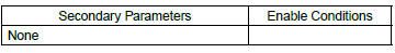
2. ENABLE CONDITION
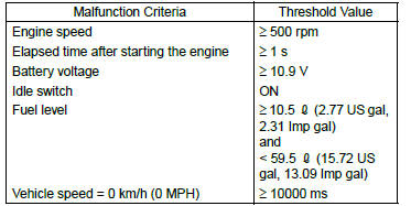
3. GENERAL DRIVING CYCLE
- Always perform the diagnosis continuously at idle speed.
- Pay attention to the fuel level.
4. DIAGNOSTIC METHOD
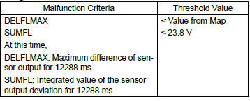
Calculate the Max. value (DELFLMAX) and cumulative value (SUMFL) of output voltage variation of fuel level sensor during 12.2 seconds. Judge it normal when both max. and cumulative values are not over the threshold value. Otherwise, when either of them is over the threshold value, the diagnosis counter counts up. Judge as NG if the counter indicated 4 time(s).
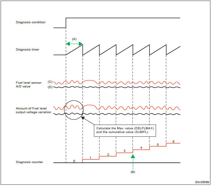
- 12288 ms
- NG at 4 time(s) counts
- Malfunction
- Normal
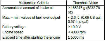
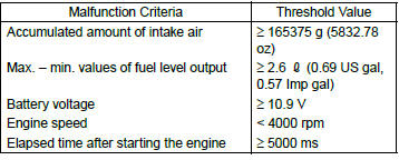
- Abnormality Judgment
If the duration of time while the following conditions are met is longer than the time indicated, judge as NG.
Judgment Value
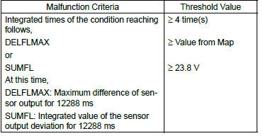
Map

The diagnosis counter does not count up when the following conditions are completed within 12288 ms.
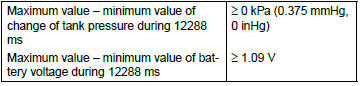
Time Needed for Diagnosis: 12288 ms × 4 time(s)
Malfunction Indicator Light Illumination: Illuminates when malfunction occurs in 2 continuous driving cycles.
- Normality Judgment
Judge as OK and clear the NG if the continuous time while the following conditions are established is more than the predetermined time.
Judgment Value
Time Needed for Diagnosis: 12288 ms
READ NEXT:
 DTC P0500, P0506, P0507, P050A, P050B, P0512, P0513, P0604, P0605, P0607,
P0638, P0700, P0851, P0852
DTC P0500, P0506, P0507, P050A, P050B, P0512, P0513, P0604, P0605, P0607,
P0638, P0700, P0851, P0852
CJ:DTC P0500 VEHICLE SPEED SENSOR "A"
1. OUTLINE OF DIAGNOSIS
Judge as NG when outside of the judgment value.
Judge NG when the received data from VDCCM&H/U is abnormal vehicle speed, and
the ve
DTC P1152, P1153, P1160, P1443, P1492, P1493, P1494, P1495, P1496, P1497,
P1498, P1499, P1518, P1560, P1570, P1571, P1572, P1574, P1576, P1577, P1578
CZ:DTC P1152 O2 SENSOR CIRCUIT RANGE/PERFORMANCE (LOW) (BANK1
SENSOR1)
1. OUTLINE OF DIAGNOSIS
Detect that λ value remains low.
Judge as NG when lambda value is abnormal in accordance with λ
DTC P2096, P2097, P2101, P2102, P2103, P2109, P2122, P2123, P2127, P2128,
P2135, P2138, P2227, P2228, P2229, P2610
DU:DTC P2096 POST CATALYST FUEL TRIM SYSTEM TOO LEAN (BANK 1)
1. OUTLINE OF DIAGNOSIS
Detect the malfunction of fuel system from the size of the sub feedback
learning value.
Control the sub feedback
SEE MORE:
Remote transmitter program
New transmitters can be programmed to the remote engine start system in the event
that a transmitter is lost, stolen, damaged or additional transmitters are desired
(the system will accept up to eight transmitters). New remote engine start transmitters
can be programmed according to the follow
Knock Sensor
A: REMOVAL
1) Disconnect the ground cable from battery.
2) Remove the cover (A) and clip (B) from air intake
boot assembly.
3) Loosen the clamp (A) which connects the air intake
boot assembly and air cleaner case.
4) Loosen the clamp (B) which connects the air intake
boot assembly and throttle bo
