Subaru Outback (BR): Knock Sensor
A: REMOVAL
1) Disconnect the ground cable from battery.
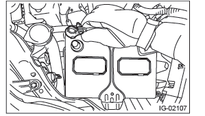
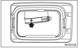
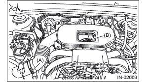
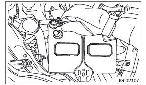
2) Remove the cover (A) and clip (B) from air intake boot assembly.
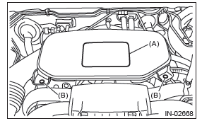
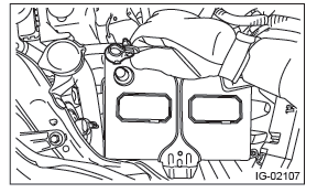
3) Loosen the clamp (A) which connects the air intake boot assembly and air cleaner case.
4) Loosen the clamp (B) which connects the air intake boot assembly and throttle body.
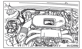
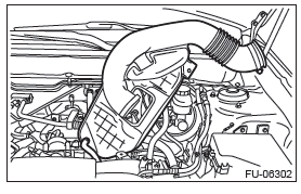
5) Remove the air intake boot from the throttle body, and move it to the left side wheel apron.
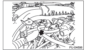
6) Disconnect the connector from the knock sensor.
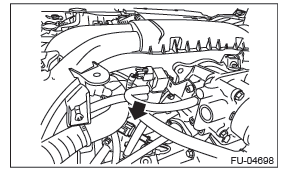
7) Remove the knock sensor from cylinder block.
B: INSTALLATION
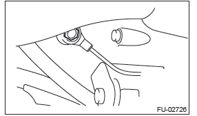
1) Install the knock sensor to the cylinder block.
NOTE: The portion of the knock sensor cord that is pulled out must be positioned at a 60º angle relative to the engine rear.
Tightening torque: 24 N*m (2.4 kgf-m, 17.7 ft-lb)
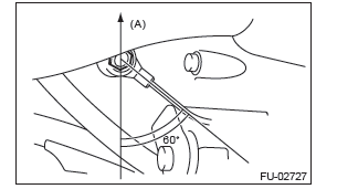
- Front side of vehicle
2) Connect the connector to the knock sensor.
3) Install the air intake boot assembly.
NOTE: Align the clamp hole with the protrusion of the air intake boot assembly.
Tightening torque:
Clamp (A), (B)
3 N*m (0.3 kgf-m, 2.2 ft-lb)
4) Connect the battery ground terminal.
C: INSPECTION
1) Check that the knock sensor has no deformation, cracks or other damages.
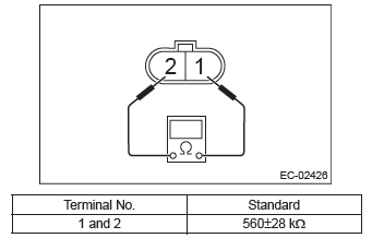
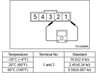
2) Measure the resistance between knock sensor terminals.
Throttle Position Sensor
A: SPECIFICATION
Throttle body is a non-disassembled part, so do not remove the throttle position sensor from throttle body.
Refer to "Throttle Body" for removal and installation procedure.
Mass Air Flow and Intake Air
Temperature Sensor
A: REMOVAL
1) Disconnect the ground cable from battery.
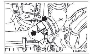
2) Disconnect the connector (A) from the mass air flow and intake air temperature sensor, and remove the mass air flow and intake air temperature sensor.
B: INSTALLATION
Install in the reverse order of removal.
Tightening torque: 1 N*m (0.1 kgf-m, 0.7 ft-lb)
C: INSPECTION
1. CHECK MASS AIR FLOW SENSOR UNIT
1) Connect the battery positive terminal to terminal No. 3 and the battery ground terminal to terminal No. 4, the circuit tester positive terminal to terminal No. 5 and the circuit tester ground terminal to terminal No. 4.
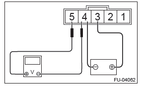
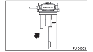
2) Check the voltage changes when air is blown to the mass air flow sensor unit in arrow direction.
2. CHECK INTAKE AIR TEMPERATURE SENSOR UNIT
Measure the resistance between intake air temperature sensor terminals.
3. OTHER INSPECTIONS
1) Check that the mass air flow and intake air temperature sensor has no deformation, cracks or other damages.
2) Check that the mass air flow and intake air temperature sensor has no dirt.
READ NEXT:
 Manifold Absolute Pressure
Sensor
Manifold Absolute Pressure
Sensor
A: REMOVAL
1) Disconnect the ground cable from battery.
2) Remove the cover (A) and clip (B) from air intake
boot assembly.
3) Loosen the clamp (A) which connects the air intake
boot assembly and ai
Oil Temperature Sensor
A: REMOVAL
1) Disconnect the ground cable from battery.
2) Remove the cover (A) and clip (B) from air intake
boot assembly.
3) Loosen the clamp (A) which connects the air intake
boot assembly and ai
Main Relay
A: REMOVAL
1) Disconnect the ground cable from battery.
2) Remove the glove box lid assembly.
3) Remove the main relay from the relay holder.
B: INSTALLATION
Install in the reverse order of removal
SEE MORE:
Front seats
WARNING
● Never adjust the seat while driving to avoid the possibility of loss of vehicle
control and of personal injury.
● Before adjusting the seat, make sure the hands and feet of rear seat passengers
or cargo are clear of the adjusting mechanism.
● After adjusting the se
Front Speaker
A: REMOVAL
1. FRONT SIDE SPEAKER
1) Disconnect the ground cable from battery.
2) Remove the front side speaker.
Release the clips and claws, then detach the speaker cover.
CAUTION:
Use a plastic clip remover for removal.
Remove the screws.
Preparation tool: Stubby screwdriver
Disconnect the
