Subaru Outback (BR): Fuses
CAUTION
Never replace a fuse with one having a higher rating or with material other than a fuse because serious damage or a fire could result.
The fuses are designed to melt during an overload to prevent damage to the wiring harness and electrical equipment. The fuses are located in two fuse boxes.
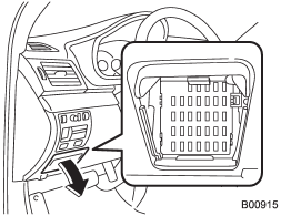
One is located under the instrument panel behind the fuse box cover on the driver’s seat side. To remove the cover, pull it out.
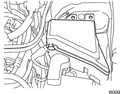
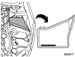
The other one is housed in the engine compartment.
The spare fuses are stored in the main fuse box cover in the engine compartment.
The fuse puller is stored in the main fuse box in the engine compartment.
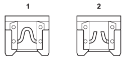
1) Good
2) Blown
If any lights, accessories or other electrical controls do not operate, inspect the corresponding fuse. If a fuse has blown, replace it.
1. Turn the ignition switch to the “LOCK” position and turn off all electrical accessories.
2. Remove the cover.
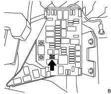
3. Determine which fuse may be blown. Look at the back side of each fuse box cover and refer to “Fuses and circuits” F12-10.
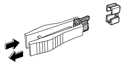
4. Pull out the fuse with the fuse puller.
5. Inspect the fuse. If it has blown, replace it with a spare fuse of the same rating.
6. If the same fuse blows again, this indicates that its system has a problem. Contact your SUBARU dealer for repairs.
READ NEXT:
 Main fuse
Main fuse box
The main fuses are designed to melt during an overload to prevent damage to the
wiring harness and electrical equipment. Check the main fuses if any electrical
component fails to
Replacing bulbs
WARNING
Bulbs may become very hot while illuminated. Before replacing bulbs, turn off
the lights and wait until the bulbs cool down, Otherwise, there is the risk of sustaining
a burn injury.
CAU
SEE MORE:
Security ID plate
1) Key number plate
2) Security ID plate
The security ID is stamped on the security ID plate attached to the key set.
Write down the security ID and keep it in another safe place, not in the vehicle.
This number is needed to make a replacement key if you lose your key or lock it
inside the
Tire Identification Number (TIN)
Tire Identification Number (TIN) is marked on the intended outboard sidewall.
The TIN is composed of four groups. Here is a brief review of the TIN with a breakdown
of its individual elements.
(1) Manufacturer’s Identification Mark
(2) Tire Size
(3) Tire Type Code
(4) Date of Manufacture
