Subaru Outback (BR): Heater Core
A: REMOVAL
1) Disconnect the ground cable from battery.
2) Using the refrigerant recovery system, discharge refrigerant. <Ref. to AC-24, PROCEDURE, Refrigerant Recovery Procedure.>
3) Drain the coolant from the radiator.
- H4 non-turbo model: <Ref. to CO(H4SO)-14, DRAINING OF ENGINE COOLANT, REPLACEMENT, Engine Coolant.>
- H4 turbo model: <Ref. to CO(H4DOTC)-14, DRAINING OF ENGINE COOLANT, REPLACEMENT, Engine Coolant.>
- H6 model: <Ref. to CO(H6DO)-12, DRAINING OF ENGINE COOLANT, REPLACEMENT, Engine Coolant.>
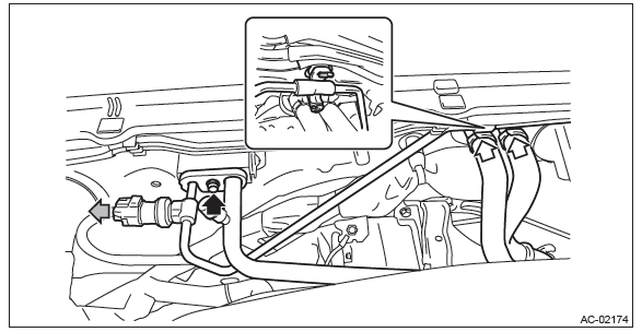
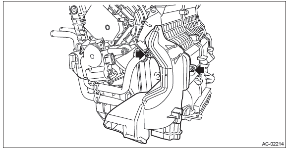
4) Remove the connector and bolts, and remove the high-pressure hose and AC pipe from the expansion valve.
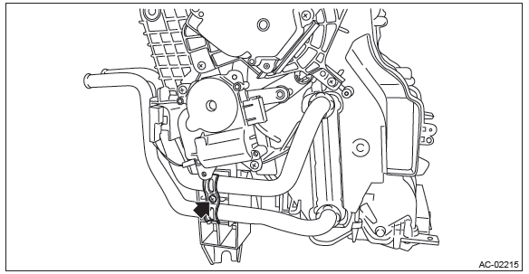
5) Loosen the heater hose clamps and remove the hoses.
6) Remove the instrument panel assembly. <Ref. to EI-76, REMOVAL, Instrument Panel Assembly.>
7) Remove the engine control module (ECM).
- Release the lock and remove the relay holder.
- Remove the nuts, and remove the engine control module (ECM).
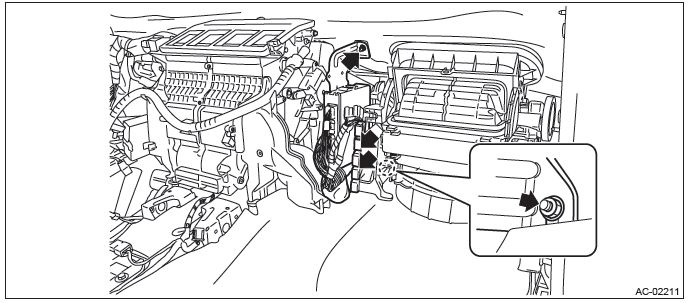
8) Remove the heater and cooling unit.
- Remove the bolt and remove the heater and cooling unit.
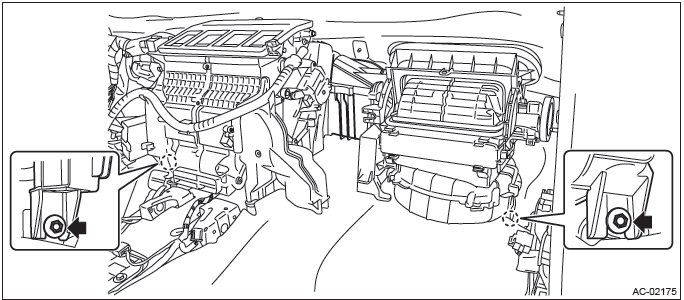
9) Disconnect the claws and then remove the aspirator hose.
10) Remove the screws and remove the foot duct (LH).
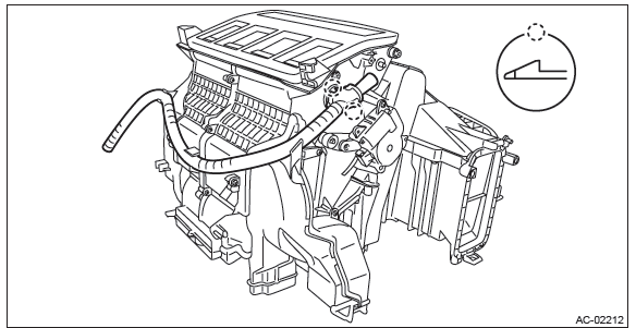
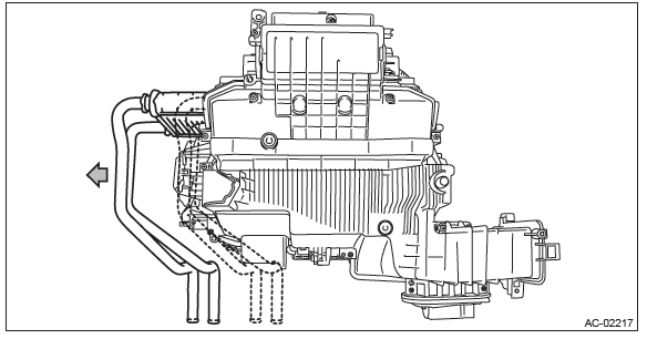
11) Remove the heater core.
- Remove the screw and remove the heater pipe clamp.
- Pull out the heater core from the heater and cooling unit assembly.
B: INSTALLATION
CAUTION:
- Do not start the engine before charging refrigerant.
- If the engine is started with no refrigerant charge, replace the compressor.
- Replace O-rings and pipe clamps with new parts and install securely.
1) Install each part in the reverse order of removal.
NOTE: Refer to "INSTALLATION" of "Instrument Panel Assembly". <Ref. to EI-95, INSTALLATION, Instrument Panel Assembly.>
2) Fill engine coolant.
- H4 non-turbo model: <Ref. to CO(H4SO)-14, FILLING OF ENGINE COOLANT, REPLACEMENT, Engine Coolant.>
- H4 turbo model: <Ref. to CO(H4DOTC)-14, FILLING OF ENGINE COOLANT, REPLACEMENT, Engine Coolant.>
- H6 model: <Ref. to CO(H6DO)-12, FILLING OF ENGINE COOLANT, REPLACEMENT, Engine Coolant.>
3) Charge refrigerant. <Ref. to AC-25, PROCEDURE, Refrigerant Charging Procedure.>
Tightening torque:
Heater cooling unit: <Ref. to AC-6, HEATER COOLING UNIT, COMPONENT, General
Description.>
Blower motor unit: <Ref. to AC-8, BLOWER MOTOR UNIT, COMPONENT, General
Description.>
READ NEXT:
 HVAC System Control Panel
A: REMOVAL
1. AUTO A/C MODEL
1) Disconnect the ground cable from battery.
2) Remove the center panel assembly.
CAUTION: Do not put your finger on the fin of the air vent grille. Doing so may damag
Heater and Cooling Unit
A: REMOVAL
1) Disconnect the ground cable from battery.
2) Using the refrigerant recovery system, discharge refrigerant. <Ref. to AC-24,
PROCEDURE, Refrigerant
Recovery Procedure.>
3) Drain t
Evaporator
A: REMOVAL
1) Disconnect the ground cable from battery.
2) Using the refrigerant recovery system, discharge refrigerant. <Ref. to AC-24,
PROCEDURE, Refrigerant
Recovery Procedure.>
3) Drain t
SEE MORE:
Rear wiper
To turn the rear wiper on, turn the knob on the end of the wiper control lever
upward to the “INT” or “ON” position. To turn the wiper off, return the knob on
the end of the lever to the “OFF” position. With the switch turned to the “INT”
position, the rear wiper will operate i
Scalp Cap
A: REPLACEMENT
1. MODEL WITHOUT ELECTRIC RETRACTABLE MIRROR
CAUTION:
When removing the mirror, be careful not to damage the back surface
of mirror with a flat tip screwdriver.
When installing the mirror, insert the connector and clip securely.
1) Operate the remote control mirror switch to fac
