Subaru Outback (BR): Relay and Fuse, Door Lock Control System
A: LOCATION
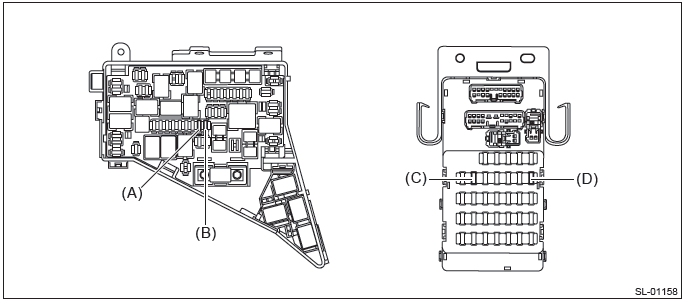
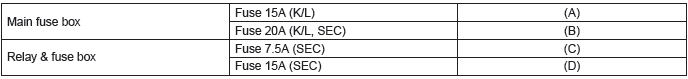
NOTE: For other related fuses, refer to the wiring diagram. <Ref. to WI-15, Power Supply Circuit.>
B: INSPECTION
1. CHECK FUSE.
1) Remove the fuse and inspect visually.
2) If the fuse is blown out, replace the fuse.
NOTE: If the fuse is blown again, check the system wiring harness.
Door Lock Control System
A: WIRING DIAGRAM
Refer to "Keyless Entry System" in the wiring diagram. <Ref. to WI-181, WIRING DIAGRAM, Keyless Entry System.>
B: ELECTRICAL SPECIFICATION
1. BODY INTEGRATED UNIT
Refer to "Control Module I/O Signal" of "BODY CONTROL SYSTEM (DIAGNOSTICS)" section. <Ref. to BC(diag)-7, ELECTRICAL SPECIFICATION, Control Module I/O Signal.>
C: INSPECTION
1. SYMPTOM CHART
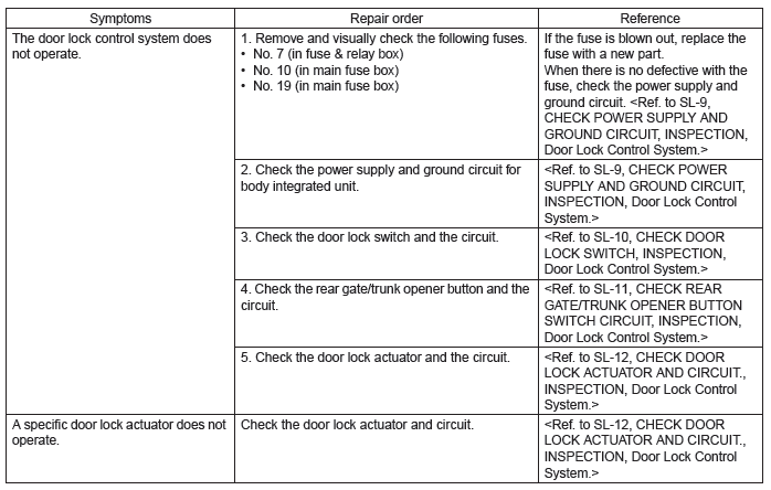
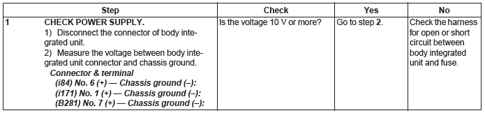
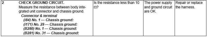
2. CHECK POWER SUPPLY AND GROUND CIRCUIT
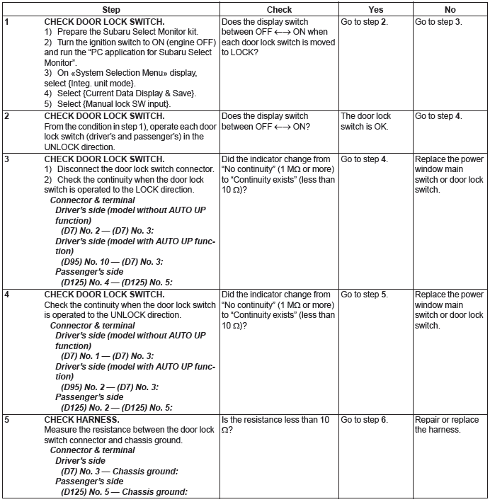
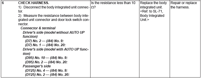
3. CHECK DOOR LOCK SWITCH
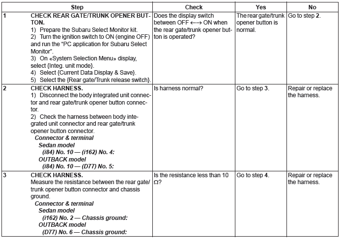
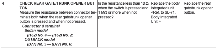
4. CHECK REAR GATE/TRUNK OPENER BUTTON SWITCH CIRCUIT
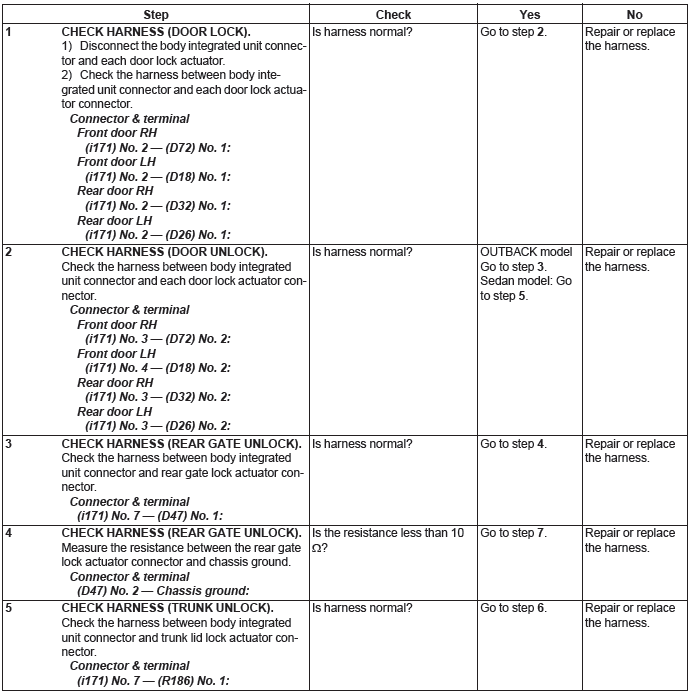
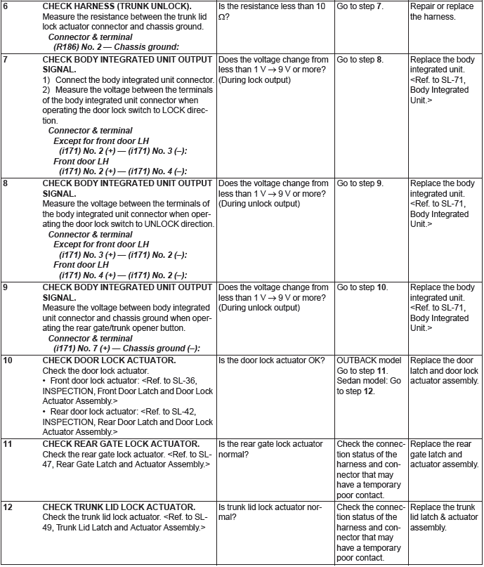
5. CHECK DOOR LOCK ACTUATOR AND CIRCUIT
READ NEXT:
 Keyless Entry System
A: WIRING DIAGRAM
Refer to "Keyless Entry System" in the wiring diagram. <Ref. to WI-181,
WIRING DIAGRAM, Keyless Entry
System.>
B: ELECTRICAL SPECIFICATION
1. KEYLESS ENTRY CONTROL MODULE
Mo
Front Inner Remote
A: REMOVAL
1) Remove the door trim. <Ref. to EI-60, REMOVAL, Door Trim.>
2) Remove the screws to detach the front inner remote handle.
B: INSTALLATION
1) Before installation, check the followi
Rear Inner Remote
A: REMOVAL
1) Remove the door trim. <Ref. to EI-60, REMOVAL, Door Trim.>
2) Remove the screws and detach the rear inner remote handle.
B: INSTALLATION
1) Before installation, check the followi
SEE MORE:
Front Differential Assembly in Manual Transmission
A: REMOVAL
1) Remove the manual transmission assembly from the vehicle. <Ref. to 6MT-25, REMOVAL, Manual Transmission Assembly.>
2) Remove the transfer case together with the extension case assembly. <Ref. to 6MT-40, REMOVAL, Transfer Case and Extension Case Assembly.>
3) Remove the t
Drive Pinion Shaft Assembly in Continuously Variable Transmission
A: REMOVAL
1) Remove the transmission assembly from the vehicle. <Ref. to CVT-55, REMOVAL, Automatic Transmission Assembly.>
2) Remove the air breather hose. <Ref. to CVT-132, REMOVAL, Air Breather Hose.>
3) Remove the oil pan and control valve body. <Ref. to CVT-111, REMOVAL, Con
