Subaru Outback (BR): Keyless Entry System
A: WIRING DIAGRAM
Refer to "Keyless Entry System" in the wiring diagram. <Ref. to WI-181, WIRING DIAGRAM, Keyless Entry System.>
B: ELECTRICAL SPECIFICATION
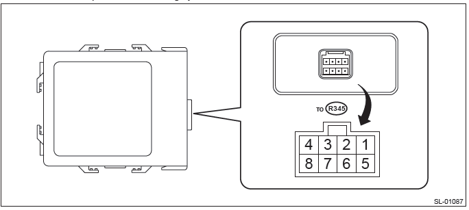
1. KEYLESS ENTRY CONTROL MODULE
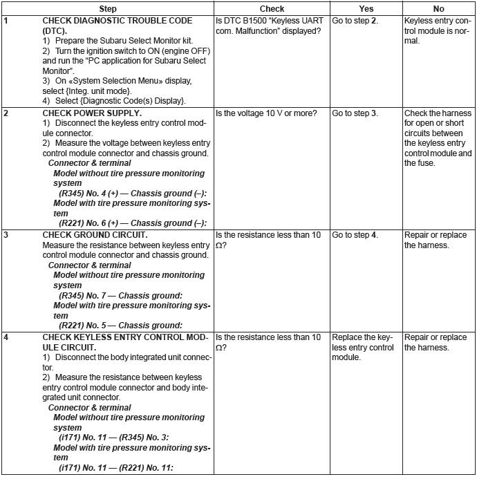
- Model without tire pressure monitoring system
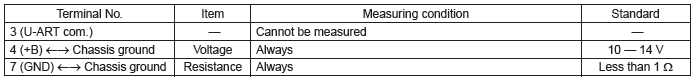
- Model with tire pressure monitoring system
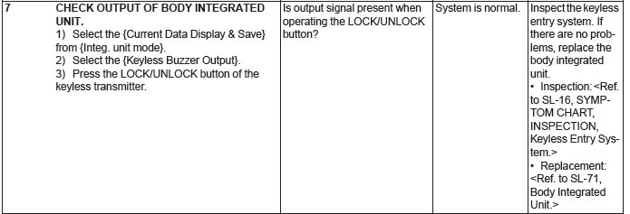
2. BODY INTEGRATED UNIT
Refer to "Control Module I/O Signal" of "BODY CONTROL SYSTEM (DIAGNOSTICS)" section. <Ref. to BC(diag)-7, ELECTRICAL SPECIFICATION, Control Module I/O Signal.>
C: INSPECTION
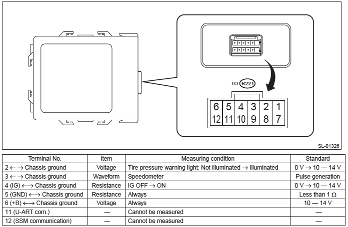
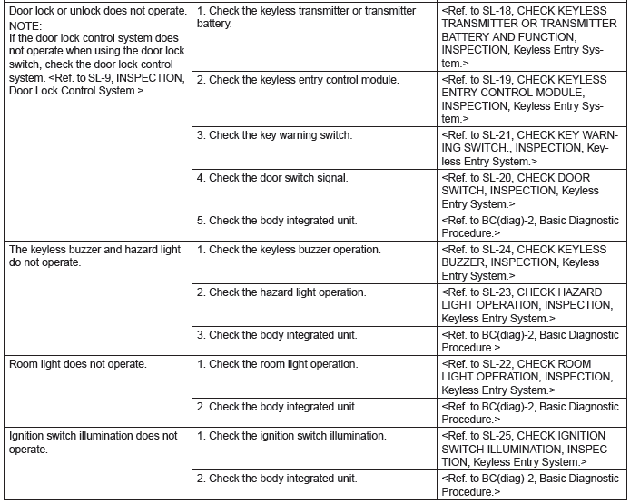
1. SYMPTOM CHART
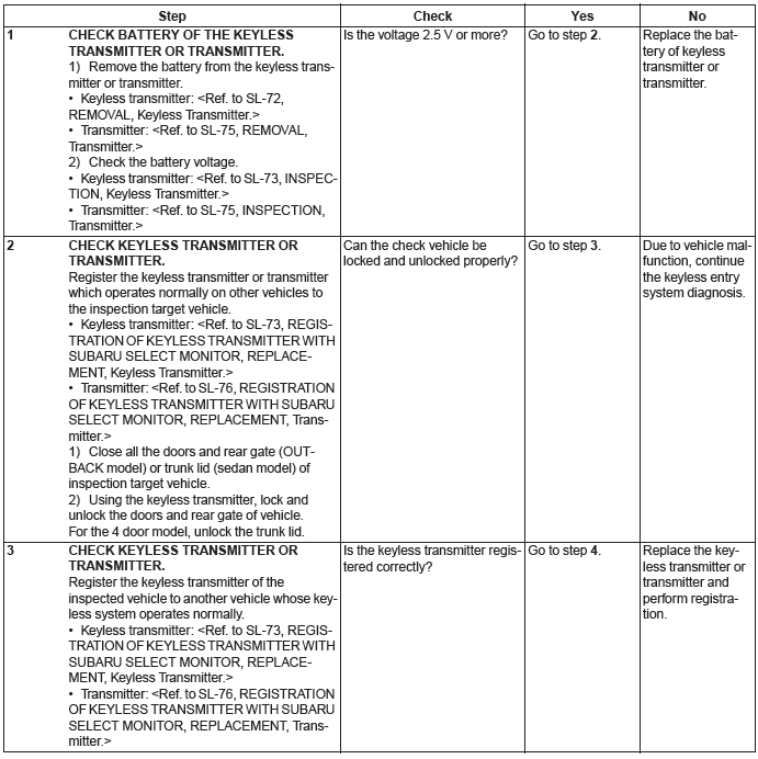
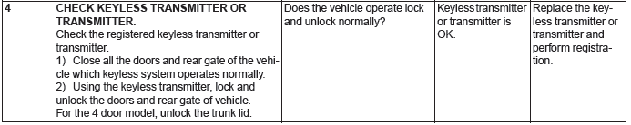
2. CHECK KEYLESS TRANSMITTER OR TRANSMITTER BATTERY AND FUNCTION
CAUTION: Be sure to reset keyless transmitter or transmitter of other vehicles registered to the inspection target vehicle, and vehicles to which keyless transmitters or transmitter were registered for inspection, to the condition before performing the inspection. (Re-register the keyless transmitters or transmitter.)
3. CHECK KEYLESS ENTRY CONTROL MODULE
4. CHECK BODY INTEGRATED UNIT POWER SUPPLY AND GROUND CIRCUIT
Refer to the "INSPECTION of POWER SUPPLY AND GROUND CIRCUIT" of "Door Lock Control System" for detailed procedures. <Ref. to SL-9, CHECK POWER SUPPLY AND GROUND CIRCUIT, INSPECTION, Door Lock Control System.>
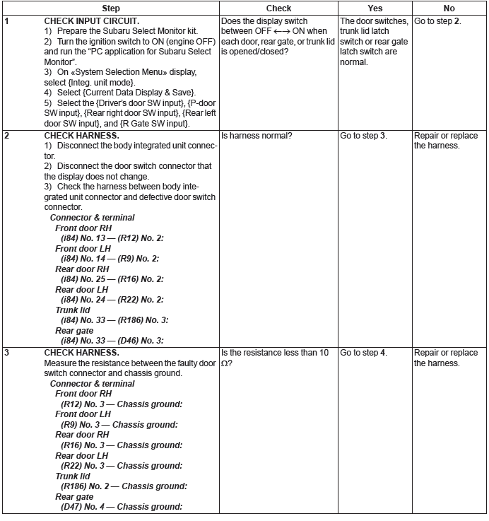
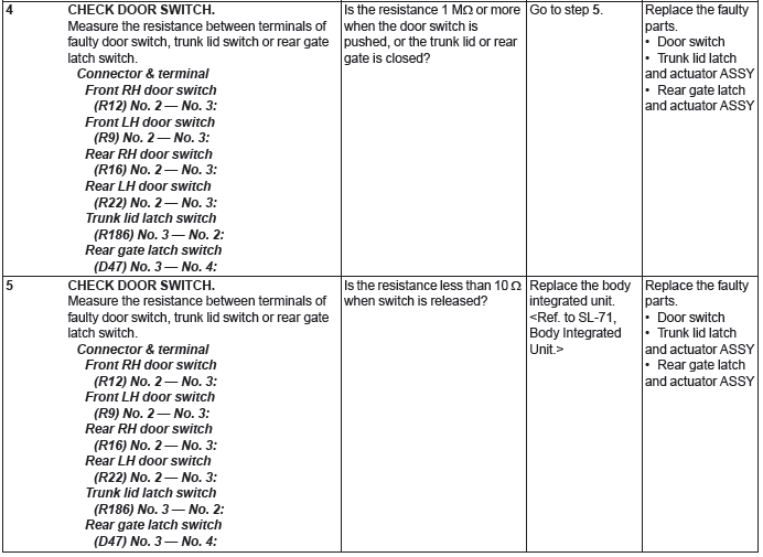
5. CHECK DOOR SWITCH
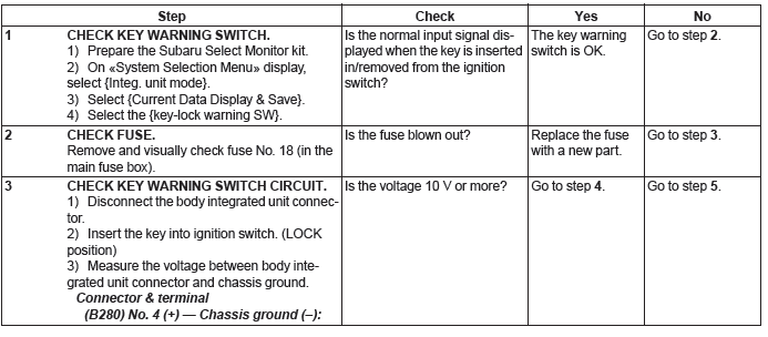
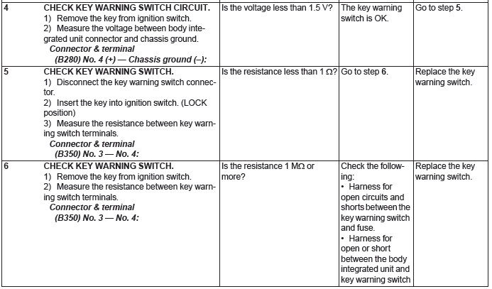
6. CHECK KEY WARNING SWITCH
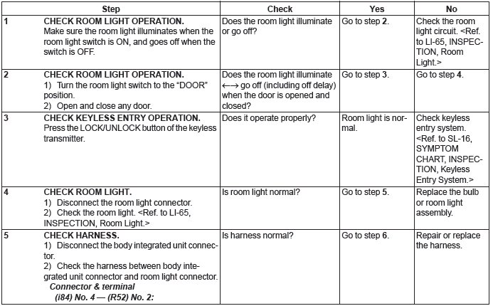
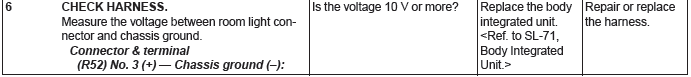
7. CHECK ROOM LIGHT OPERATION
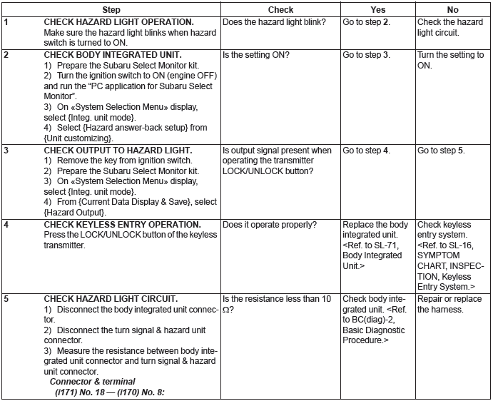
8. CHECK HAZARD LIGHT OPERATION
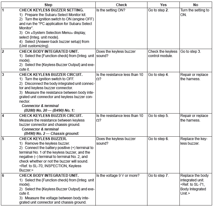
9. CHECK KEYLESS BUZZER
10.CHECK DOOR LOCK SWITCH
For procedures, refer to the "INSPECTION OF DOOR LOCK SWITCH" of the "Door Lock Control System".
<Ref. to SL-10, CHECK DOOR LOCK SWITCH, INSPECTION, Door Lock Control System.>
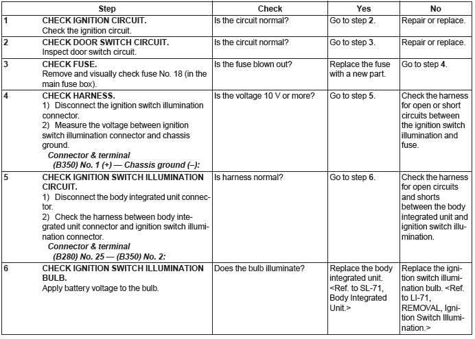
11.CHECK IGNITION SWITCH ILLUMINATION
Security System
A: WIRING DIAGRAM
Refer to "Security System" in the wiring diagram. <Ref. to WI-236, WIRING DIAGRAM, Security System.>
B: ELECTRICAL SPECIFICATION
Refer to "Control Module I/O Signal" of "BODY CONTROL SYSTEM (DIAGNOSTICS)" section. <Ref. to BC(diag)-7, ELECTRICAL SPECIFICATION, Control Module I/O Signal.>
C: INSPECTION
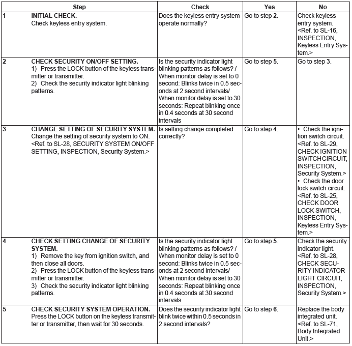
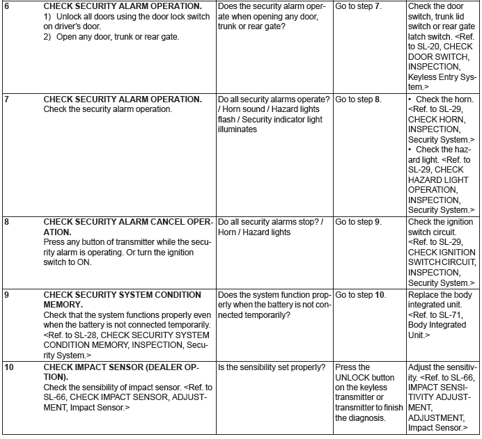
1. BASIC DIAGNOSTIC PROCEDURE
NOTE: If the horn sounds when the security is turned on (monitor condition) using the keyless transmitter, check the function setting of the body integrated unit. As a cause, it is possible that the impact sensor present (ON) / not present (OFF) setting is set to ON in the customization function though there is no impact sensor. <Ref. to BC(diag)-16, User Customizing.>
2. CHECK SECURITY SYSTEM CONDITION MEMORY
1) Pull out the key from the ignition switch, or turn the ignition to OFF.
2) Close all the doors, trunk lid and rear gate.
3) Open the front hood.
4) Press the LOCK button of the keyless transmitter or transmitter.
NOTE: Wait until the security indicator light blinks twice within 0.5 seconds at 2 second intervals.
If the 30 second monitoring lag has been set, wait for 30 seconds.
5) Disconnect the ground cable from battery.
6) Connect the battery ground terminal.
7) Check that the security indicator light blinks twice within 0.5 seconds at 2 second intervals. When it does not blink, replace the body integrated unit.
3. SECURITY SYSTEM ON/OFF SETTING
1) Close all doors, trunk lid and rear gate, and sit down on the driver seat. Press the UNLOCK button of the keyless transmitter or transmitter.
2) Turn the ignition switch to ON.
3) Press the central door lock switch and open the driver's door simultaneously. (Keep the central door lock switch pressed down.)
4) When the condition in step 3) continues for 10 seconds, the system switches to a mode reverse to the current mode.

4. CHECK DOOR SWITCH
For operation procedure, refer to "CHECK DOOR SWITCH" of "Keyless Entry System". <Ref. to SL-20, CHECK DOOR SWITCH, INSPECTION, Keyless Entry System.>
5. CHECK SECURITY INDICATOR LIGHT CIRCUIT
For operation procedures, refer to "CHECK SECURITY INDICATOR LIGHT CIRCUIT" of "IMMOBILIZER (DIAGNOSTICS)" section. <Ref. to IM(diag)-11, CHECK SECURITY INDICATOR LIGHT CIRCUIT, INSPECTION, Diagnostics Chart for Security Indicator Light.>
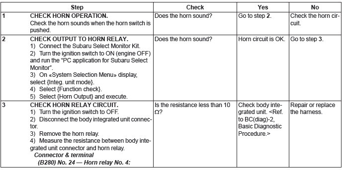
6. CHECK HORN
7. CHECK HAZARD LIGHT OPERATION
For operation procedure, refer to "CHECK HAZARD LIGHT OPERATION" of "Keyless Entry System". <Ref. to SL-23, CHECK HAZARD LIGHT OPERATION, INSPECTION, Keyless Entry System.>
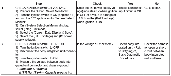
8. CHECK IGNITION SWITCH CIRCUIT
READ NEXT:
 Front Inner Remote
A: REMOVAL
1) Remove the door trim. <Ref. to EI-60, REMOVAL, Door Trim.>
2) Remove the screws to detach the front inner remote handle.
B: INSTALLATION
1) Before installation, check the followi
Rear Inner Remote
A: REMOVAL
1) Remove the door trim. <Ref. to EI-60, REMOVAL, Door Trim.>
2) Remove the screws and detach the rear inner remote handle.
B: INSTALLATION
1) Before installation, check the followi
Rear Gate Latch and Actuator Assembly
A: REMOVAL
1) Disconnect the ground cable from battery.
2) Remove the rear gate trim. <Ref. to EI-160, REMOVAL, Rear Gate Trim.>
3) Remove the rear gate latch & actuator assembly.
Remove
SEE MORE:
Front Fender
A: REMOVAL
1) Disconnect the ground cable from battery.
2) Remove the bumper face assembly.
Remove the clips, turn over the front mud guard, and disconnect the fog
light connector. (Model with
fog light)
Remove the clips at the upper side of the bumper.
Remove the clips from the fender.
Transfer Case and Extension
Case Assembly
A: REMOVAL
1) Remove the manual transmission assembly
from the vehicle. <Ref. to 6MT-25, REMOVAL,
Manual Transmission Assembly.>
2) Remove the back-up light switch and the neutral
position switch. <Ref. to 6MT-37, REMOVAL,
Switches and Harness.>
3) Remove the transfer case together wit
