Subaru Outback (BR): Starter
A: REMOVAL
1) Disconnect the ground cable from battery.
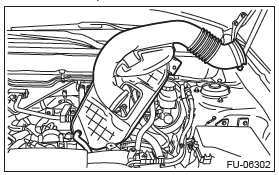
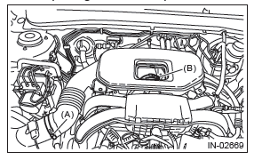
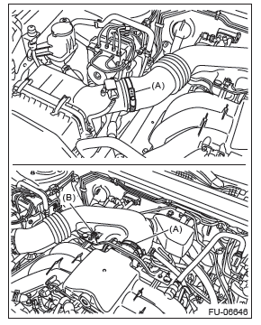
2) Remove the cover (A) and clip (B) from air intake boot assembly. (2.5 L non-turbo model)
3) Loosen the clamp (A) which connects the air intake boot assembly and air cleaner case. (2.5 L non-turbo model)
4) Loosen the clamp (B) which connects the air intake boot assembly and throttle body. (2.5 L non-turbo model)
5) Remove the air intake boot from the throttle body, and move it to the left side wheel apron. (2.5 L non-turbo model)
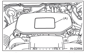
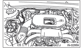
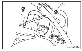
6) Loosen the clamp (A) which connects the air intake boot assembly. (3.6 L model)
7) Loosen the bolt (B) which secures the air intake boot assembly to the collector cover bracket. (3.6 L model)
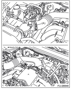
8) Remove the air intake boot assembly, and move it to the left side wheel apron. (3.6 L model)
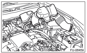
9) Remove the intercooler. (turbo model) <Ref. to IN(H4DOTC)-17, REMOVAL, Intercooler.>
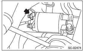
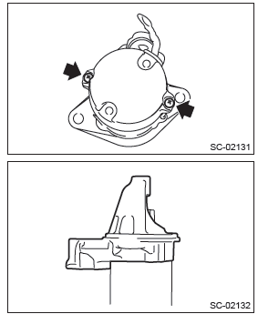
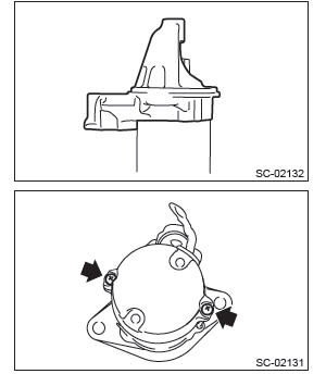
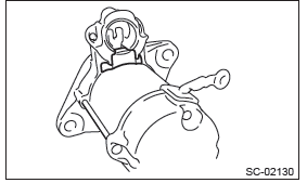
10) Disconnect the connector (B) and terminal (A) from starter.
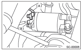
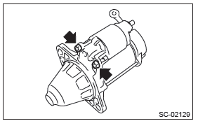
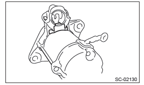
11) Remove the starter from transmission.
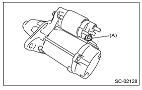
NOTE: For the MT model, a bolt is used in place (A).
B: INSTALLATION
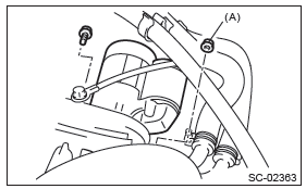
Install in the reverse order of removal.
NOTE: For the MT model, a bolt is used in place (A).
Tightening torque: 50 N*m (5.1 kgf-m, 36.9 ft-lb)
Tightening torque: 10 N*m (1.0 kgf-m, 7.4 ft-lb)
- 2.5 L non-turbo model
NOTE: Align the clamp hole with the protrusion of the air intake boot assembly.
Tightening torque:
Clamp (A), (B)
3 N*m (0.3 kgf-m, 2.2 ft-lb)
- 3.6 L model
Tightening torque:
Clamp (A)
3 N*m (0.3 kgf-m, 2.2 ft-lb)
Bolt (B)
6.5 N*m (0.7 kgf-m, 4.8 ft-lb)
C: DISASSEMBLY
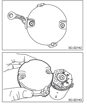
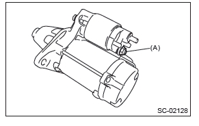
1) Remove the nut which holds terminal M (A) of the magnet switch assembly, then disconnect the harness from the terminal.
2) Remove the nuts fastening the magnet switch assembly to the starter housing, then remove the magnet switch assembly.
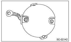
3) Remove the starter seal.
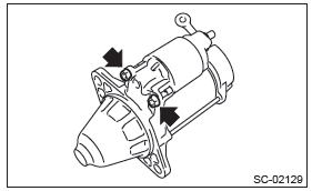
4) Remove the through bolts on both sides, and remove the starter housing.
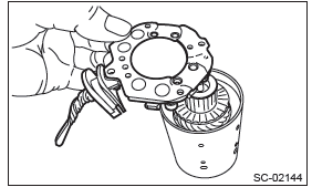
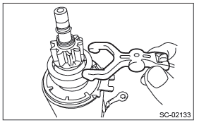
5) Remove the shift lever.
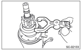
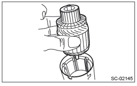
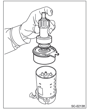
6) Remove the overrunning clutch assembly from the yoke.
7) Remove the starter plate.
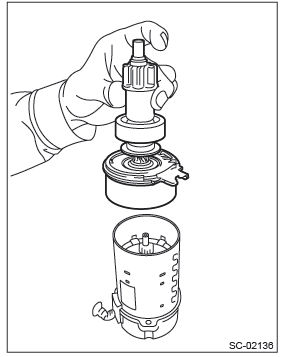
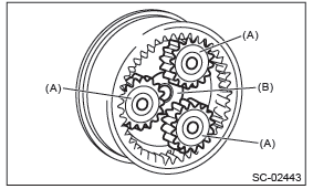
8) Remove the planetary gear (A) and washer (B) from internal gear.
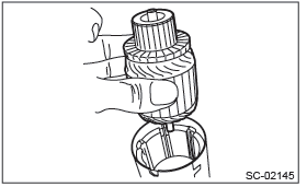
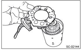
9) Remove the screws, and remove the starter cover from the brush holder assembly.
NOTE: Separate the starter cover by pressing the brush holder assembly using the screws so that the assembly stays onto the armature side.
10) Remove the brush holder assembly from the armature.
NOTE: Spread the brush with your fingers, being careful not to damage the brush.
11) Remove the armature from the yoke.
D: ASSEMBLY
1) Install the armature to the yoke.
2) Install the brush holder assembly to the armature.
NOTE: Spread the brush with your fingers, being careful not to damage the brush.
3) Install the starter cover, and secure it to the brush holder assembly with the screws.
4) Assemble the planetary gear (A) and washer (B) to the internal gear.
- Apply grease to the planetary gear installation position.
Grease: DENSO HL50
- Install the planetary gear to the pin.
- Apply grease to the planetary gear, internal gear, washer, and upper part of the pin.
NOTE:
- Apply grease so that it contacts each gear.
- Be careful not to allow dirt to get in.
Grease: DENSO HL50
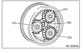
- Install the starter plate.
5) Assemble the overrunning clutch assembly to the yoke.
6) Install the shift lever.
NOTE: Apply grease to the contact portion of the shift lever.
Grease: DENSO HL50
7) Install the starter housing, and tighten through bolts on both sides.
Tightening torque: 6 N*m (0.6 kgf-m, 4.4 ft-lb)
8) Install the starter seal.
9) Install the magnet switch assembly to the starter housing, and tighten the nuts.
NOTE: Apply grease to the shift lever installation position.
Grease: DENSO HL50
Tightening torque: 7.5 N*m (0.8 kgf-m, 5.5 ft-lb)
10) Install the harness to the terminal M (A) of the magnet switch assembly, and tighten the nut.
Tightening torque: 10 N*m (1.0 kgf-m, 7.4 ft-lb)
E: INSPECTION
1. SWITCH ASSEMBLY
Using a circuit tester (set to "ohm"), check that there is continuity between terminals S and M, and between terminal S and ground.
Also check to be sure there is no continuity between terminals M and B.
Terminal/Resistance:
S - M/1 Ω or less
S - Ground/1 Ω or less
M - B/1 MΩ or more
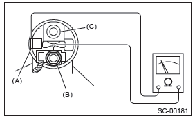
- Terminal S
- Terminal M
- Terminal B
2. SWITCH ASSEMBLY OPERATION
NOTE: Perform each test in a short period of time (3 - 5 sec).
1) Suction test
Check that the pinion gear comes flying out when the harness is disconnected from terminal M and connected as shown in the figure.
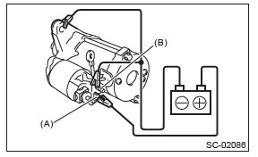
- Terminal S
- Terminal M
2) Holding test
Check that the pinion gear remains flying out after the cable is disconnected from terminal M.
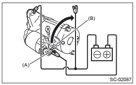
- Terminal S
- Terminal M
3) Returning test
With terminal S connected to the positive terminal, and terminal M and starter body connected to the battery ground terminal to suction the main contact point, check that the pinion gear returns to its original position when terminal S is disconnected.
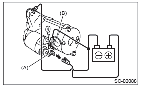
- Terminal S
- Terminal M
3. PERFORMANCE TEST
The starter should be submitted to performance tests whenever it has been overhauled, to assure its satisfactory performance when installed on the engine.
Three performance tests, no-load test, load test, and lock test, are presented here; however, if the load test and lock test cannot be performed, carry out at least the no-load test.
For these performance tests, use the circuit shown in figure.
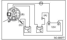
- Variable resistance
- Magnetic switch
- Starter body
1) No-load test
Adjust the variable resistance with the switch on until the voltage is 11 V, and read the value displayed on the ammeter to measure rotating speed.
Compare these values with the standard.
No-load test (standard):
Voltage/Current
Max. 11 V/90 A or less
Rotating speed
2.5 L model
1,900 rpm or more
3.6 L model
1,550 rpm or more
2) Load test
Apply the specified braking torque to starter. The condition is normal if the current draw and rotating speed are within standard.
Load test (standard):
Voltage/Load
2.5 L model
8 V/11.1 N*m (1.1 kgf-m, 8.2 ft-lb) or more
3.6 L model
8 V/12.8 N*m (1.3 kgf-m, 9.4 ft-lb) or more
Current/Rotating speed
2.5 L model
370 A/910 rpm or more
3.6 L model
370 A/800 rpm or more
3) Lock test
With the starter stalled, or not rotating, measure the torque developed and current draw when the voltage is adjusted to standard voltage.
Lock test (standard):
Voltage/Current
3 V/750 A or less
Torque
2.5 L model
15.5 N*m (1.6 kgf-m, 11.4 ft-lb) or more
3.6 L model
19.0 N*m (1.9 kgf-m, 14.0 ft-lb) or more
4. OTHER INSPECTIONS
Check that the starter does not have deformation, cracks and any other damage.
READ NEXT:
 Generator
A: REMOVAL
1) Disconnect the ground cable from battery.
2) Remove the V-belts. <Ref. to ME(H4SO)-43, VBELT,
REMOVAL, V-belt.> <Ref. to
ME(H4DOTC)-42, V-BELT, REMOVAL, V-belt.>
<Ref. t
Battery (inspection, removal, installation)
A: REMOVAL
1) After disconnecting the battery ground terminal, remove the terminal cover, then disconnect the positive terminal.
2) Remove the battery cable holder from the battery rod.
3) Remove
SEE MORE:
Seatbelt warning light and chime
NOTE
If your seatbelt warning device does not operate as described in the following,
it may be out of order. Have the device inspected and, if necessary, repaired by
the nearest SUBARU dealer.
Your vehicle is equipped with a seatbelt warning device at the driver’s and front
passenger’s s
Cruise Control System
General Description
A: COMPONENT
Engine control module (ECM)
Cruise control command switch
Stop light and brake switch
Cruise indicator light and cruise
set indicator light
Transmission control module
(TCM) (AT and CVT model)
Inhibitor switch (CVT model)
Neutral position switch (MT
model
