Subaru Outback (BR): Wheel and Tire System
General Description
A: SPECIFICATION
- Offset
- P.C.D.
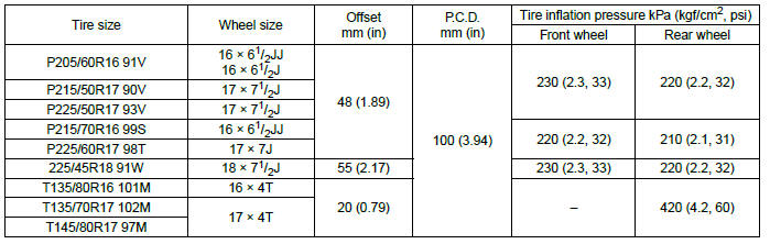
NOTE:
Size and inflation pressure of the standard equipment tire and spare tire for emergency are described on the "Tire inflation pressure" label attached to the body side of the driver's door.
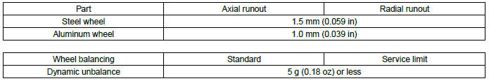
1. SERVICE DATA
B: COMPONENT
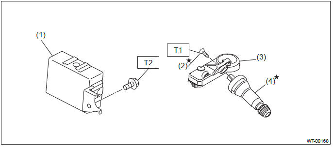
- TPMS & keyless entry control module
- Screw
- Transmitter (snap in type)
- Valve
Tightening torque: N*m (kgf-m, ft-lb)
T1: 1.4 (0.14, 1.0)
T2: 7.5 (0.76, 5.5)
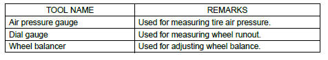
C: PREPARATION TOOL
1. GENERAL TOOL
Tire and Wheel
A: REMOVAL
1) Remove the hubcap.
2) Lift up the vehicle.
3) Remove the wheel nut.
4) Remove the wheels.
CAUTION: When removing the wheels, be careful not to damage the hub bolts.
B: INSTALLATION
1) Install the wheels to vehicle.
2) Tighten the wheel nuts to the specified torque.
Tightening torque: 120 N*m (12.24 kgf-m, 88.5 ft-lb)
C: INSPECTION
1. TIRE
CAUTION: When replacing a tire, make sure to use only tires of the same size, construction and load range as originally installed.
1) Tire size and tire inflation pressure check <Ref. to WT-2, SPECIFICATION, General Description.>
2) Cracks, damage and wear check
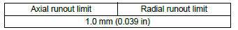
3) Tire runout check
- Lift up the vehicle.
- Slowly rotate the wheel to check rim "runout" using a dial gauge.
- Aluminum wheel
- Steel wheel
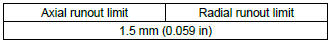
- If the rim runout exceeds service limit, replace the wheel.
2. TIRE ROTATION
NOTE:
Rotate tires periodically (12,500 km/7,500 miles) in order to prolong life and to prevent uneven wear. Rotate tires as shown in the figure depending on whether or not the direction of the tire rotation is specified.
- When the direction of tire rotation is not specified
- Front side of vehicle
- When the direction of tire rotation is specified
- Front side of vehicle
3. WHEEL BALANCING
1) Using the wheel balancer, measure wheel balance.
2) Adjust the wheel balancing.
NOTE:
- Unbalance after adjusting the wheel balancing should be 5 g (0.18 oz) or less.
- When using the adhesive type weight, degrease the surface where the adhesive type weight will be applied securely.
- After applying the adhesive type weight, apply a force to the weight and attain full adhesion.
- Using the knock-on type weight, check the size of the knock-on part.
- Knock-on type weight for aluminum wheel
- Knock-on type weight for steel wheel
Service limit A:
Knock-on type weight for steel wheel: 2.0 mm (0.079 in)
Knock-on type weight for aluminum wheel: 5.0 mm (0.197 in)
"T-type" Tire
A: NOTE
"T-type" tire for temporary use is prepared as a spare tire.
CAUTION:
- The "T-type" tire is only for temporary use. Replace with a conventional tire as soon as possible.
- Do not use tire chains for "T-type" tires. Doing so can damage the vehicle and the tires because the tires are too small in size to attach chains to.
- Do not drive at a speed greater than 80 km/h (50 MPH).
- Drive at as low a speed as possible and avoid bumps on the road.
B: REPLACEMENT
Refer to "Tire & Wheel" for removal and installation of the "T-type" tire. <Ref. to WT-4, Tire and Wheel.>
C: INSPECTION
Refer to "Tire & Wheel" for inspection of the "T-type" tire. <Ref. to WT-4, TIRE, INSPECTION, Tire and Wheel.>
Tire Pressure Monitoring System
A: REMOVAL
1. TRANSMITTER (TIRE INFLATION PRESSURE SENSOR)
1) Remove the wheels from the vehicle. <Ref. to WT-4, REMOVAL, Tire and Wheel.>
2) Remove the tires from wheels.
CAUTION: Use a tire changer when removing the tire from the wheel.
3) Loosen the screw to remove the transmitter from the valve stem.
CAUTION: Do not reuse the valve and screw. Replace the valve and screw with a new part even when reusing transmitter.
- Wheel
- Transmitter
- Screw
- Valve
4) Remove the valve from the wheel.
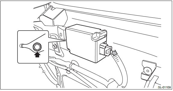
2. TPMS & KEYLESS CONTROL MODULE
NOTE: TPMS control module is integrated with the keyless entry control module.
Sedan model
1) Disconnect the ground cable from battery.
2) Remove the rear shelf trim. <Ref. to EI-120, REMOVAL, Rear Shelf Trim.>
3) Remove the TPMS & keyless control module.
- Disconnect the connector.
- Remove the bolt and then remove the TPMS & keyless control module.
OUTBACK model
1) Disconnect the ground cable from battery.
2) Remove the rear quarter trim LH. <Ref. to EI-110, REMOVAL, Rear Quarter Trim.>
3) Remove the TPMS & keyless control module.
- Disconnect the connector.
- Remove the bolt and then remove the TPMS & keyless control module.
B: INSTALLATION
1. TRANSMITTER (TIRE INFLATION PRESSURE SENSOR)
CAUTION: Use the new transmitter assembly or replace the new valve and screw, when installing.
1) Replace the valve and screw with a new part when reusing transmitter.
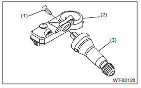
- Screw
- Transmitter
- Valve
Tightening torque: 1.4 N*m (0.14 kgf-m, 1.0 ft-lb)
2) Install the transmitter to the wheel by aligning it with valve hole.
NOTE: When using the jig that pulls the valve cap by hooking its neck part, use another short-type cap.
3) Install the tires to wheels.
CAUTION:
- Use a tire changer when installing tire to wheel.
- To prevent damaging the transmitter, set the tire changer boom in the position as shown in the figure.
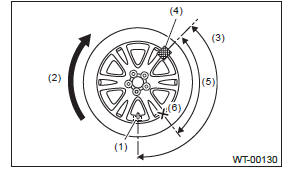
- Transmitter
- Direction of turn table rotation
- 135º
- Tire changer boom
- 90º
- Starting point for fitting the bead to the rim
4) Install the wheels to vehicle. <Ref. to WT-4, INSTALLATION, Tire and Wheel.>
5) Register the transmitter ID to the TPMS & keyless control module. <Ref. to TPM(diag)-12, Register Transmitter (ID).>
2. TPMS & KEYLESS CONTROL MODULE
Install each part in the reverse order of removal.
Tightening torque: 7.5 N*m (0.76 kgf-m, 5.5 ft-lb)
C: ADJUSTMENT
Re-register the transmitter ID when transmitter has been replaced. <Ref. to TPM(diag)-12, Register Transmitter (ID).>
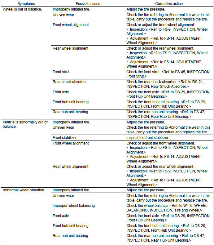
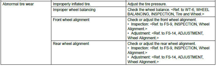
General Diagnostic Table
A: INSPECTION
READ NEXT:
 Tire Pressure Monitoring System (Diagnostics)
Basic Diagnostic Procedure
A: PROCEDURE
CAUTION:
Before removal or installation, be sure to remove any foreign matter (dust,
moisture, oil, etc.) from
the TPMS & keyless entry control module conn
General Description of Differentials
A: SPECIFICATION
1. REAR DIFFERENTIAL
When replacing a rear differential assembly, select the correct one according to the following table.
NOTE:
Using a different rear differential assembl
SEE MORE:
General Description of the Seats
A: COMPONENT
1. FRONT SEAT
Manual seat LH
Backrest heater ASSY
Backrest pad
Backrest cover
Backrest frame ASSY
Backrest back cover
Headrest bushing
Headrest ASSY
Flat mat hook
S hook
Side airbag module ASSY
Side airbag tape
Se
Windshield washer fluid
CAUTION
Never use engine coolant as washer fluid because it could cause paint damage.
If you spray washer fluid on the windshield but the windshield washer fluid warning
light illuminates or the supply of washer fluid runs out, add washer fluid in the
tank.
Remove the washer tank filler
