Subaru Outback (BR): FRESH/RECIRC Door Actuator
A: REMOVAL
1) Set the intake door actuator to RECIRC position.
- Turn the ignition switch to ON.
- Operate the control panel and switch to RECIRC mode.
- In the condition of step (2), turn the ignition switch to OFF.
2) Remove the instrument panel assembly. <Ref. to EI-76, REMOVAL, Instrument Panel Assembly.>
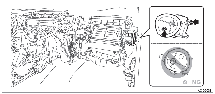
3) Remove the screw, and remove the intake door actuator.
B: INSTALLATION
Install each part in the reverse order of removal.
NOTE: Refer to "INSTALLATION" of "Instrument Panel Assembly". <Ref. to EI-95, INSTALLATION, Instrument Panel Assembly.>
C: INSPECTION
1. ACTUATOR LINK
1) Visually check the operating range of the link, and remove the foreign matter if any.
2) Operate the FRESH/RECIRC switch, and check that the link operates normally.
3) If the actuator does not operate normally, check the intake door actuator unit.
2. CHECK ACTUATOR OPERATION
1) Check the actuator operation when battery voltage is applied between the terminals of intake door actuator.
CAUTION: Disconnect the battery immediately after the actuator stops operation. Otherwise, the motor may be damaged.
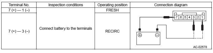
2) If the actuator does not operate normally, replace the intake door actuator.
Mode Door Actuator
A: REMOVAL
1) Remove the instrument panel lower cover. <Ref. to EI-64, REMOVAL, Instrument Panel Lower Cover.>
2) Remove the bolt and detach the knee protector.
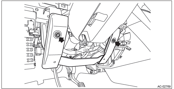
3) Remove the body integrated unit.
CAUTION: Be careful to keep water and other foreign materials away from body integrated unit.
- Remove the harness clip and connector.
- Remove the bolts, and remove the body integrated unit.
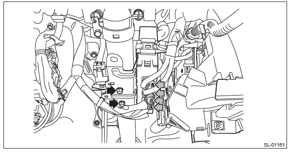
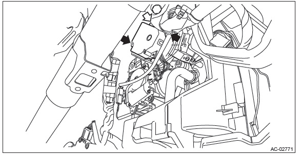
4) Remove the mode door actuator.
- Disconnect the connector.
- Remove the screws, and remove the mode door actuator.
B: INSTALLATION
Install each part in the reverse order of removal.
C: INSPECTION
1. ACTUATOR LINK
1) Visually check the operating range of the link, and remove the foreign matter if any.
2) Operate the mode change switch, and check that the link operates normally.
3) If the actuator does not operate normally, check the mode door actuator unit.
2. CHECK ACTUATOR OPERATION
Preparation tool: Circuit tester
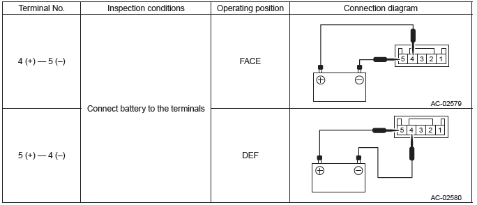
1) Check the actuator operation when battery voltage is applied between the terminals of mode door actuator.
CAUTION: Disconnect the battery immediately after the actuator stops operation. Otherwise, the motor may be damaged.
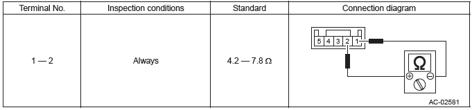
2) Check the resistance between terminals of the mode door actuator.
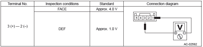
3) Connect the mode door actuator connector, turn the ignition switch to ON and check the voltage between terminals of the mode door actuator.
4) Replace the mode door actuator if it is found defective.
READ NEXT:
 Air Mix Door Actuator
A: REMOVAL
1. DRIVER'S SEAT
1) Remove the instrument panel lower cover. <Ref. to EI-64, REMOVAL,
Instrument Panel Lower Cover.>
2) Remove the bolts, and remove the knee guard panel.
3) Remove
Heater Duct
A: REMOVAL
1) Remove the front seats. <Ref. to SE-10, REMOVAL, Front Seat.>
2) Remove the instrument panel face assembly. <Ref. to EI-76, REMOVAL,
Instrument Panel Assembly.>
3) Remove
SEE MORE:
Lower Inner Trim
A: REMOVAL
1) Release the claws, and then remove the side sill cover-front INN.
CAUTION:
Do not pull with excessive force. Doing so may damage the claws of the side sill
cover INN.
NOTE:
To release the claws of the side sill cover INN, the following steps are
recommended.
1. Take out the weather
Rear Hub Unit Bearing
A: REMOVAL
1) Lift up the vehicle, and then remove the rear wheels.
2) Remove the axle nut.
CAUTION:
Do not loosen the axle nut while the rear axle is loaded. Doing so may damage
the hub bearing.
Lift the crimped section of axle nut.
Remove the axle nut using a socket wrench while depressing th
