Subaru Outback (BR): Antenna
A: REMOVAL
1. RADIO ANTENNA AMPLIFIER
- Sedan model
1) Remove the rear quarter trim LH. <Ref. to EI-110, SEDAN MODEL, REMOVAL, Rear Quarter Trim.>
2) Remove the radio antenna amplifier assembly.
- Disconnect the connector.
- Remove the bolts, and then remove the radio antenna amplifier assembly.
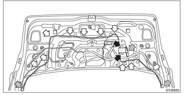
- OUTBACK model
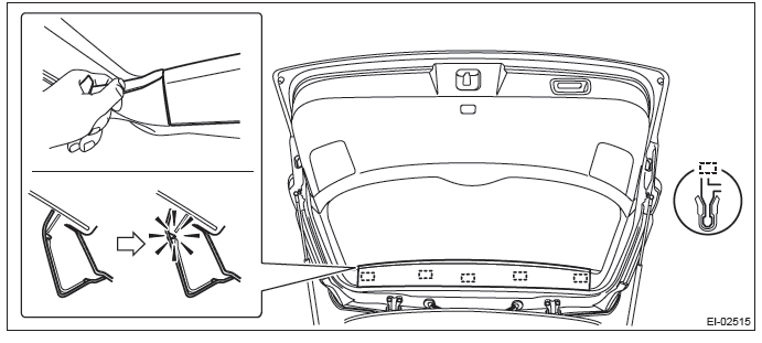
1) Remove the rear gate upper trim.
- Remove the claws on the trim edge.
- Disconnect the claws in the center of trim, and remove the rear gate upper trim.
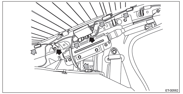
2) Remove the radio antenna amplifier assembly.
- Disconnect the connector.
- Remove the bolts, and then remove the radio antenna amplifier assembly.
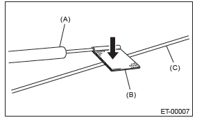
2. XM SATELLITE RADIO ANTENNA
1) Remove the roof trim. <Ref. to EI-131, REMOVAL, Roof Trim.>
2) Disconnect the harness connector and terminal, and remove the mounting nut (A).
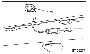
3) Pull out the antenna from the roof top.
B: INSTALLATION
Install each part in the reverse order of removal.
Tightening torque:
Radio antenna amplifier: 12 N*m (1.22 kgf-m, 8.9 ft-lb)
XM satellite radio antenna: 4.5 N*m (0.46 kgf-m, 3.3 ft-lb)
C: INSPECTION
CAUTION: When wiping dirt off of the glass to avoid heat wire damage, be careful of the following.
- Use a dry and soft cloth.
- Move the cloth along the heat wire.
Inspection method of antenna, it is different from printing pattern of antenna.
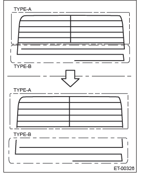
TYPE-A Printing pattern of grid
TYPE-B Printing pattern of straight
1. TYPE A
1) Disconnect the ground cable from battery.
2) Remove the trim.
Sedan model: Remove the rear quarter trim rear on both sides. <Ref. to EI-110, SEDAN MODEL, REMOVAL, Rear Quarter Trim.>
OUTBACK model: Remove the rear gate trim. <Ref. to EI-160, REMOVAL, Rear Gate Trim.>
3) Disconnect the antenna harness connector and antenna terminals.
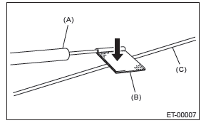
4) Prepare the extension harness (A), (B).
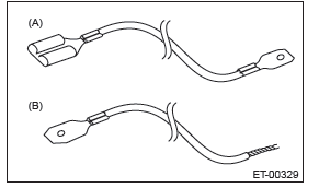
- Attach the flat terminals (male and female) to both ends of the harness of 2,000 mm (78.7 in) length (electrical wire unit dimensions approx. 2.0 mm2 (0.0032 sq in) ).
- Attach the flat terminal (female) to one side of the harness, another side to twist the harness of 2,000 mm (78.7 in) length (electrical wire unit dimensions approx. 2.0 mm2 (0.0032 sq in) ).
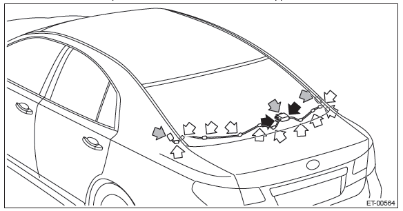
5) Connect the extension harness (A) to rear defogger harness (power supply side) terminal and antenna terminal.
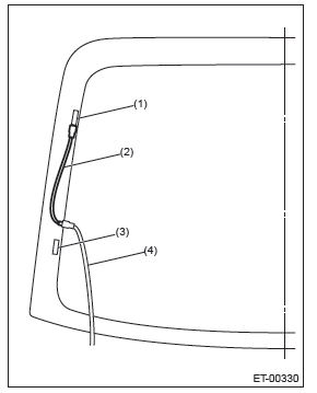
- Antenna terminal
- Extension harness (A)
- Rear defogger terminal
- Rear defogger harness (power supply side - red blue)
6) Connect the extension harness (B) to rear defogger harness (ground side) terminal.
7) Fasten the another side of extension harness (B) to end of antenna pattern of grid with tape.
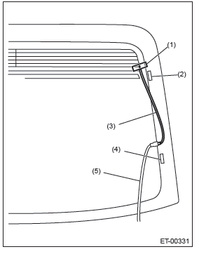
- Tape
- Antenna terminal
- Extension harness (B)
- Rear defogger terminal
- Rear defogger harness (ground side - black)
8) Connect the ground cable to battery.
9) Turn the ignition switch to ON.
10) Turn the rear defogger switch to ON.
11) Wrap a piece of aluminum foil around the tip of tester probe and press foil against antenna wire with your finger.
- Tester probe
- Aluminum foil
- Antenna wire
12) Measure the voltage around an antenna wire (a) and (b).
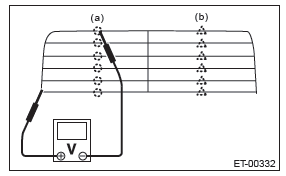

NOTE:
Measuring point (a)
- If the measured value is 6 V, heat wire is open between antenna wire center and positive (+) terminal of probe.
- If it is 0 V, the circuit is open between antenna wire center and ground.
Measuring point (b)
- If the measured value is 12 V, heat wire is open between antenna wire center and positive (+) terminal of probe.
- If it is 6 V, the circuit is open between antenna wire center and ground.
13) Fasten the voltmeter positive (+) side and negative (-) side to end of open harness positive side of step 12).
14) Search a point the voltage changes from 0 V, and move the negative (-) probe along antenna wire slowly.
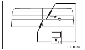
15) Repair the antenna wire if the place of the open circuit is identified. <Ref. to ET-29, REPAIR, Antenna.>
2. TYPE B
Measure the resistance between the antenna terminal and each antenna wire.
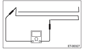
1) Disconnect the ground cable from battery.
2) Wrap a piece of aluminum foil around the tip of probe and press foil against antenna wire with your finger.
- Tester probe
- Aluminum foil
- Antenna wire
3) To locate the broken point, move the probe along antenna wire.
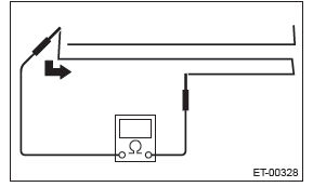
NOTE: If an antenna wire is OK, resistance will be less than 20 Ω.
If an antenna wire is broken, resistance will be more than 1 MΩ.
4) Repair the antenna wire if the place of the open circuit is identified. <Ref. to ET-29, REPAIR, Antenna.>
D: REPAIR
1) Clean the external circumference of antenna wire and around with alcohol or white gasoline.
2) Paste a thin masking film on the glass along broken wire.
3) Apply the conductive silver composition (DUPONT No. 4817) on the broken portion with a drawing pen.
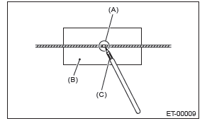
- Broken portion
- Masking film
- Conductive silver composition
4) Dry out the deposited portion.
5) After repair has been completed, measure the resistance in repaired wire.
Noise Suppressor
A: REMOVAL
1. SEDAN MODEL
1) Disconnect the ground cable from battery.
2) Remove the rear shelf trim. <Ref. to EI-120, REMOVAL, Rear Shelf Trim.>
3) Remove the noise suppressor.
- Disconnect harness connector from noise suppressor.
- Remove the harness clamps and bolts and detach the noise suppressor.
2. OUTBACK MODEL
1) Disconnect the ground cable from battery.
2) Remove the rear gate trim. <Ref. to EI-160, REMOVAL, Rear Gate Trim.>
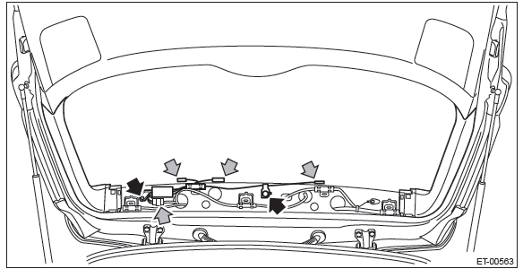
3) Remove the noise suppressor.
- Disconnect harness connector from noise suppressor.
- Remove the harness clamps and bolts and detach the noise suppressor.
B: INSTALLATION
Install each part in the reverse order of removal.
Tightening torque:
Noise suppressor: 12 N*m (1.22 kgf-m, 8.9 ft-lb)
READ NEXT:
 Steering Satellite Switch
A: REMOVAL
CAUTION:
Refer to "CAUTION" of "General Description" before handling the airbag module.
<Ref. to AB-9,
CAUTION, General Description.>
1) Position the front wheels straight ahead. (Af
GPS Antenna
A: REMOVAL
1) Disconnect the ground cable from battery.
2) Remove the center panel assembly.
CAUTION:
Do not put your finger on the fin of the air vent grille. Doing so may damage
the fin.
Attach
Rearview Camera System
A: WIRING DIAGRAM
Refer to "Rearview Camera System" in the wiring diagram. <Ref. to WI-213,
WIRING DIAGRAM, Rearview
Camera System.>
B: REMOVAL
1. SEDAN MODEL
1) Disconnect the ground cable fro
SEE MORE:
Inspection Locations after a Collision
A: REPLACEMENT
Replace the following parts if the airbag has been activated.
1. FRONT COLLISION
1) Driver's airbag module.
2) Passenger's airbag module.
3) Driver's seat belt (pretensioner).
4) Passenger's seat belt (pretensioner).
5) Airbag control module.
6) Front sub sensor (right and left).
Steering Satellite Switch
A: REMOVAL
CAUTION:
Refer to "CAUTION" of "General Description" before handling the airbag module.
<Ref. to AB-9,
CAUTION, General Description.>
1) Position the front wheels straight ahead. (After moving a vehicle 5 m (16
ft) or more with front wheels positioned
straight ahead, make sure tha
