
Subaru Outback (BR): GPS Antenna
A: REMOVAL
1) Disconnect the ground cable from battery.
2) Remove the center panel assembly.
CAUTION: Do not put your finger on the fin of the air vent grille. Doing so may damage the fin.
- Attach the protective tape (a) to the meter visor.
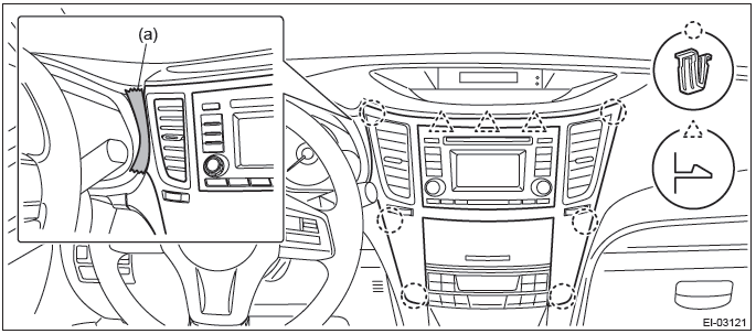
- Insert a finger into the air vent grille and release the left and right
clips at the top of the center panel.
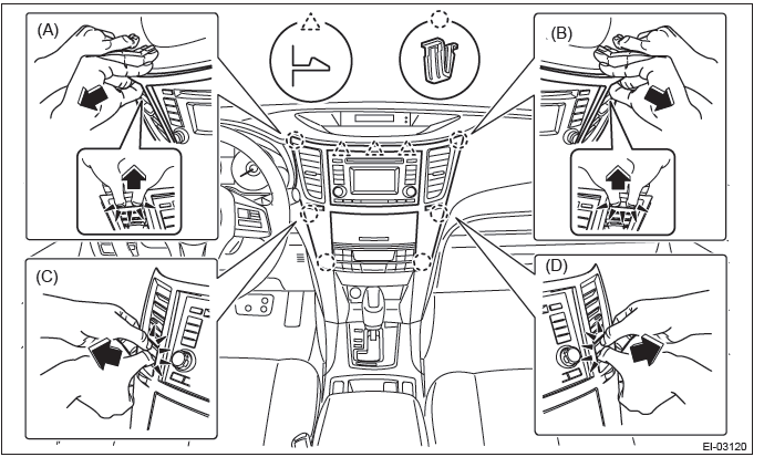
(A), (B)
- Insert a finger into the air vent grille and release the left and right
clips at the center of the center panel.
(C), (D)
- Release the clips at the bottom of the center panel and remove the center panel assembly.
3) Remove the combination meter assembly.
CAUTION:
- Be careful not to damage the meter or instrument panel.
- Pay particular attention to avoid damaging the meter glass.
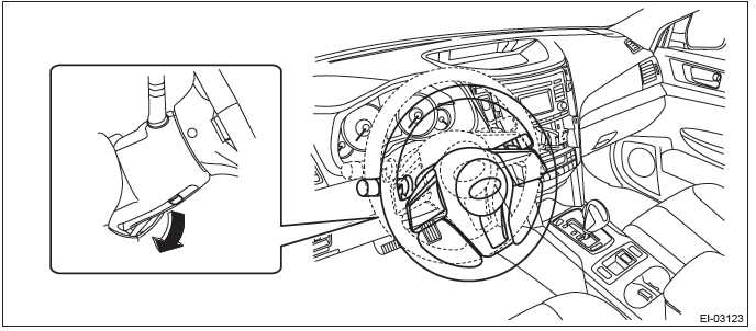
- Release the lock, tilt the steering column to the lowest end and fully extend the column by the telescopic system.
- Release the screws and clips, then detach the meter visor assembly.
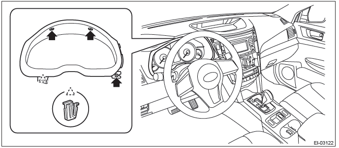
- Remove the screws and pull the steering COMPL upper cover toward you.
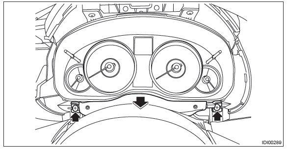
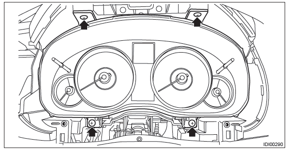
- Remove the screws and pull out the combination meter toward you to disconnect the connectors.
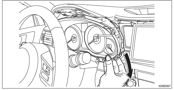
- Remove the combination meter assembly as shown in the figure.
4) Remove the navigation assembly.
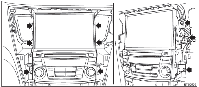
- Remove the left and right screws.
- Disconnect the connectors, and remove the navigation assembly.
5) Remove the GPS antenna.
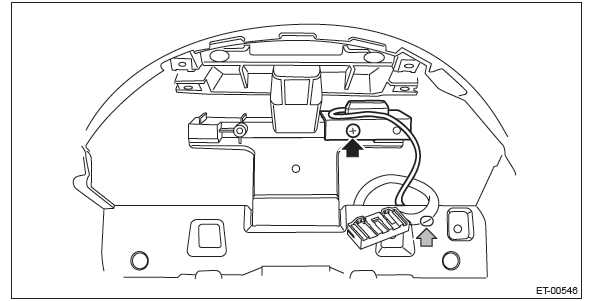
- Tie a string to the GPS antenna harness connector on the navigation assembly side.
NOTE: A string makes operation easier during installation.
- Remove the screw and harness clamp to remove the GPS antenna.
- When the GPS antenna is pulled out, remove the string attached to the connector in step (1).
B: INSTALLATION
Install each part in the reverse order of removal.
READ NEXT:
 Rearview Camera System
A: WIRING DIAGRAM
Refer to "Rearview Camera System" in the wiring diagram. <Ref. to WI-213,
WIRING DIAGRAM, Rearview
Camera System.>
B: REMOVAL
1. SEDAN MODEL
1) Disconnect the ground cable fro
Front Accessory Power Supply Socket
A: WIRING DIAGRAM
Refer to "Front Accessory Power Supply Socket System" in the wiring diagram.
<Ref. to WI-166, WIRING DIAGRAM,
Front Accessory Power Supply Socket System.>
B: REMOVAL
1) Discon
AUX Input Terminal
A: REMOVAL
1. AUX INPUT TERMINAL
1) Disconnect the ground cable from battery.
2) Remove the console front cover assembly.
MT model
1. Remove the shift knob.
2. Release the clips and claws, then p
SEE MORE:
Rearview Mirror
A: REMOVAL
CAUTION:
Be careful not to damage the mirror surface and windshield glass.
1) Remove the TORX bolt, and then slide the rear view mirror to remove.
Preparation tool: TORX T20
2) When the mirror mount is damaged, use something like piano wire or a
spatula to remove.
B: INSTALLATION
CAUTIO
LAN System - List of Diagnostic Trouble Code (DTC)
A: LIST
1. DTC TABLE
NOTE: When more than one DTC codes are recorded, referring to their combination and indicator display in the combination meter will make it easy to identify the possible cause. Refer to the list for typical examples.
Diagnostic Procedure with
© 2010-2026 Copyright www.suoutback.com
