Subaru Outback (BR): Front Accessory Power Supply Socket
A: WIRING DIAGRAM
Refer to "Front Accessory Power Supply Socket System" in the wiring diagram. <Ref. to WI-166, WIRING DIAGRAM, Front Accessory Power Supply Socket System.>
B: REMOVAL
1) Disconnect the ground cable from battery.
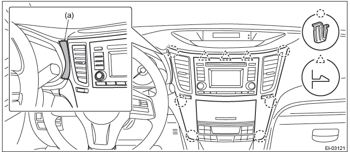
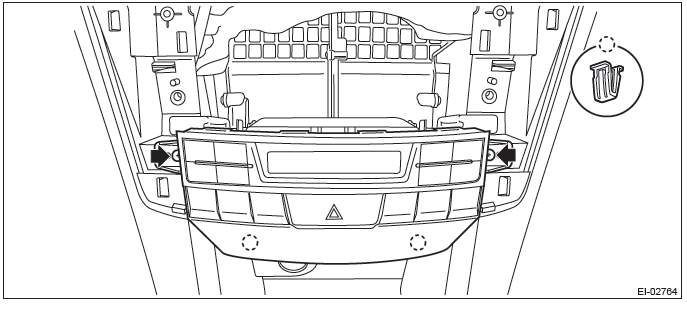
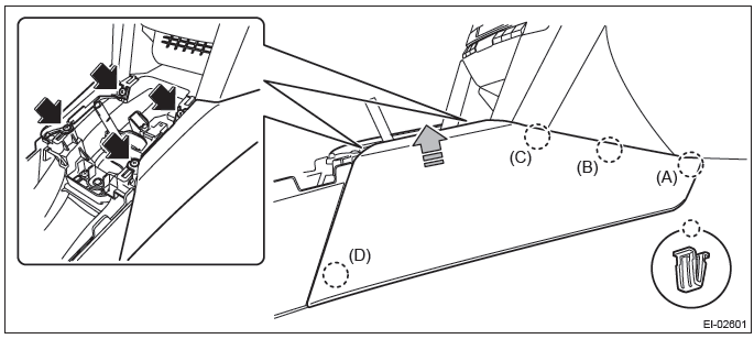
2) Remove the center panel assembly.
CAUTION: Do not put your finger on the fin of the air vent grille. Doing so may damage the fin.
- Attach the protective tape (a) to the meter visor.
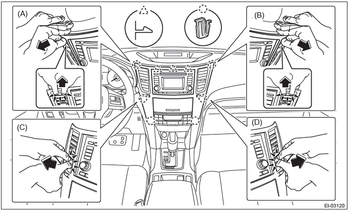
- Insert a finger into the air vent grille and release the left and right
clips at the top of the center panel.
(A), (B)
- Insert a finger into the air vent grille and release the left and right
clips at the center of the center panel.
(C), (D)
- Release the clips at the bottom of the center panel and remove the center panel assembly.
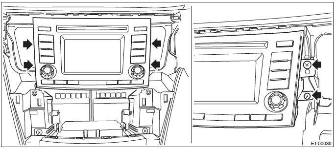
3) Remove the audio assembly.
- Remove the left and right screws, and partially pull the audio out from center console.
- Disconnect the connectors, and remove the audio assembly.
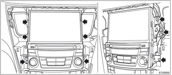
4) Remove the navigation assembly. (model with navigation)
- Remove the left and right screws.
- Disconnect the connectors, and remove the navigation assembly.
5) Remove the control panel assembly.
- Remove the screws, and pull out the control panel assembly toward you.
- Disconnect the connector, and remove the control panel assembly.
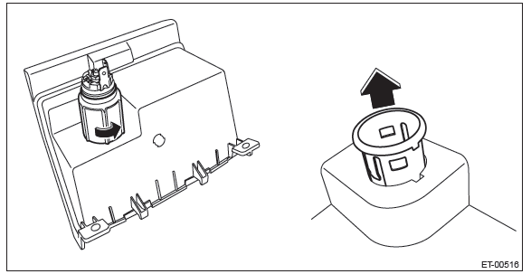
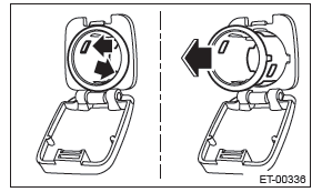
6) Remove the front accessory power supply socket.
- Disconnect the connector and turn the securing cover to remove it.
- Pull the accessory power supply socket out to remove.
C: INSTALLATION
Install each part in the reverse order of removal.
Rear Accessory Power Supply Socket
A: WIRING DIAGRAM
Refer to "Rear Accessory Power Supply Socket System" in the wiring diagram. <Ref. to WI-211, WIRING DIAGRAM, Rear Accessory Power Supply Socket System.>
B: REMOVAL
1) Remove the console front cover assembly.
- MT model
1. Remove the shift knob.
2. Release the clips and claws, then pull up the console front cover assembly.
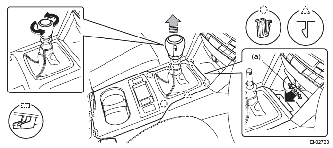
NOTE: Turn over the front center pocket mat (a) and pull up the console front cover from the slit.
3. Disconnect the harness connector and remove the console front cover assembly.
- AT/CVT model
1. Remove the select lever knob.
- Lower the cover grip AT.
- Remove the clamp grip pin, then remove the select lever knob.
2. Release the clips and claws, then pull up the console front cover assembly.
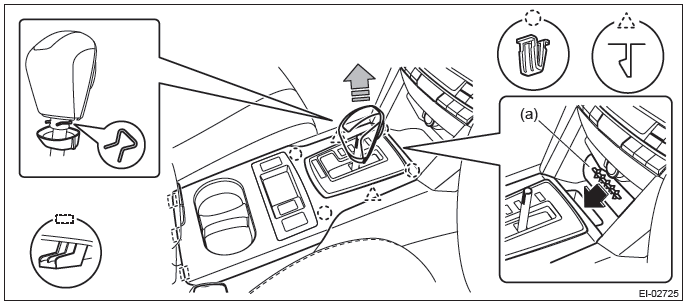
NOTE: Turn over the front center pocket mat (a) and pull up the console front cover from the slit.
3. Disconnect the harness connector and remove the console front cover assembly.
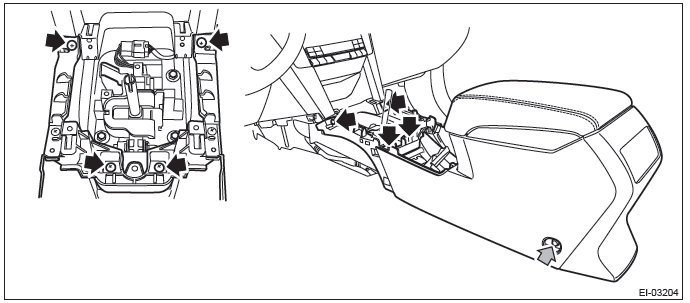
2) Remove the console front side cover assembly.
- Remove the screws and release the clips (A) to (D) in order.
- Remove the console front side cover assembly by pulling it up.
3) Remove the console box assembly.
- Move the seat forward, and remove the bolts after detaching the left and right caps.
NOTE: For a model with power seat, connect the battery ground cable and move the seat. Then, disconnect the battery ground cable again and wait for 60 seconds at least before restarting the work.
- Remove the screws, disconnect the harness connector and remove the console box assembly.
4) Remove the front accessory power supply socket.
- Remove the claws (two) in accessory power supply socket.
- Pull the accessory power supply socket out to remove.
C: INSTALLATION
Install each part in the reverse order of removal.
Tightening torque:
Center console: 6.5 N*m (0.66 kgf-m, 4.8 ft-lb)
READ NEXT:
 AUX Input Terminal
A: REMOVAL
1. AUX INPUT TERMINAL
1) Disconnect the ground cable from battery.
2) Remove the console front cover assembly.
MT model
1. Remove the shift knob.
2. Release the clips and claws, then p
Communication System
General Description
A: COMPONENT
Hi pitch side horn
Lo pitch side horn
Roll connector
Horn switch (driver's airbag module
ASSY)
Horn relay
B: CAUTION
Before disassembling or reassembling pa
SEE MORE:
Before starting out on a trip
● Check that the vehicle and vehicle-tohitch mounting are in good condition.
If any problems are apparent, do not tow the trailer.
● Check that the vehicle sits horizontally with the trailer attached. If the
vehicle is tipped sharply up at the front and down at the rear, check the t
LOCK
The key can only be inserted or removed in this position. The ignition switch
will lock the steering wheel when you remove the key.
If turning the key is difficult, turn the steering wheel slightly to the right
and left as you turn the key.
The key can be turned from “Acc” to “LOCK”
