Subaru Outback (BR): Rearview Camera System
A: WIRING DIAGRAM
Refer to "Rearview Camera System" in the wiring diagram. <Ref. to WI-213, WIRING DIAGRAM, Rearview Camera System.>
B: REMOVAL
1. SEDAN MODEL
1) Disconnect the ground cable from battery.
2) Remove the trunk lid trim.
- Remove the trunk handle.
- Remove the clips and the trunk lid trim.
3) Remove the trunk lid garnish.
- Remove the nut.
- Remove the clips and the trunk lid garnish.
4) Remove the rearview camera.
CAUTION: Do not drop or apply any impact to the rearview camera because it is a precision equipment.
- Disconnect the rearview camera connector.
- Remove the bolt from the face of trunk.
- Disconnect the claws and then remove the rearview camera assembly.
2. OUTBACK MODEL
1) Disconnect the ground cable from battery.
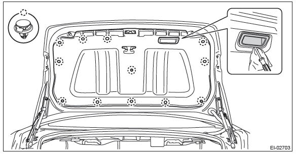
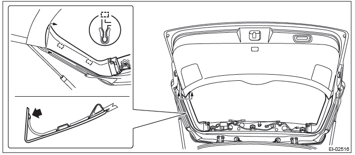
2) Remove the rear gate trim.
- Remove the rear gate upper trim.
- Remove the claws on the trim edge.
- Disconnect the claws in the center of trim, and remove the rear gate upper trim.
- Remove the rear gate pillar trim.
- Release the claws.
- Remove the claws on the bottom of trim, and remove the rear gate pillar trim.
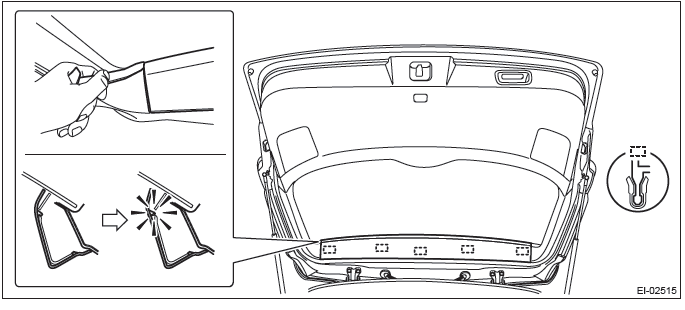
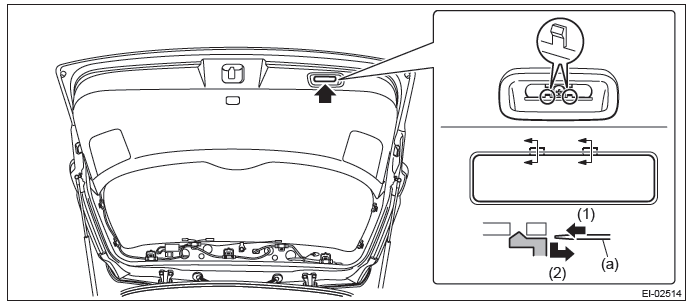
- Remove the hand grip of rear gate.
CAUTION:
- Be careful not to scratch the trim.
- To protect the trim from damage, attach a protective tape to the tool in use.
- Insert a precision screwdriver (a).
- With the screwdriver inserted, push it down to release the claw and pull it toward you.
- Remove the screws and detach the hand grip.
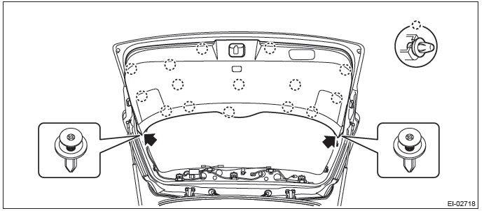
- Remove the rear gate lower trim.
- Remove the clips on both ends.
- Release the clips and remove the rear gate lower trim.
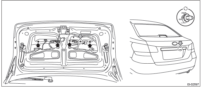
3) Remove the rear gate garnish.
- Release the clips and claws, then detach the rear finisher light side cover.
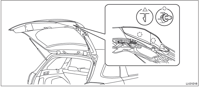
- Disconnect the harness connector of license plate light assembly.
- Remove the nuts.
- Remove the clips, and remove the rear gate garnish.
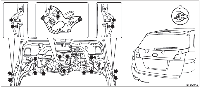
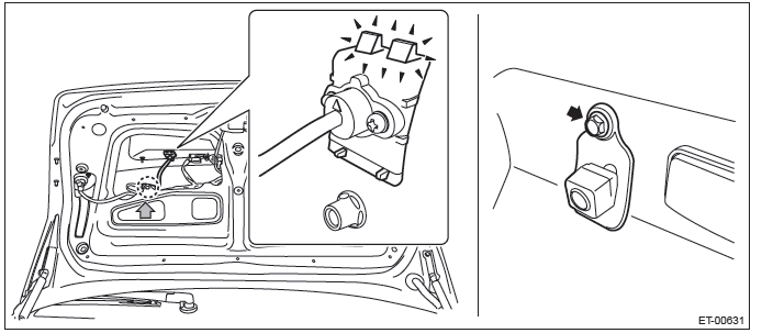
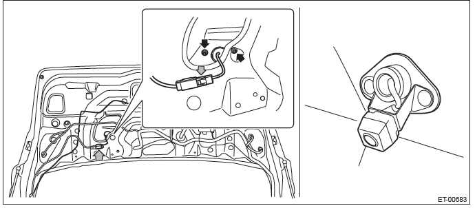
4) Remove the rearview camera assembly.
CAUTION: Do not drop or apply any impact to the rearview camera because it is a precision equipment.
- Disconnect the rearview camera connector.
- Remove the nut and bolt on the back side of rear gate.
- Disconnect the claws (for temporary fastening) and remove the rearview camera assembly.
C: INSTALLATION
CAUTION: Be sure to confirm the marker position, whenever the rearview camera is removed/installed/replaced.
Install each part in the reverse order of removal.
Tightening torque:
Sedan model
Rearview camera (bracket): 7.5 N*m (0.76 kgf-m, 5.5 ft-lb)
Trunk lid garnish: 4.5 N*m (0.46 kgf-m, 3.3 ft-lb)
OUTBACK model
Rearview camera (bracket (nut) ): 4.5 N*m (0.46 kgf-m, 3.3 ft-lb)
Rear gate garnish: 4.5 N*m (0.46 kgf-m, 3.3 ft-lb)
Rear wiper motor & wiper arm: <Ref. to WW-4, REAR WIPER, COMPONENT, General
Description.>
D: INSPECTION
1) Park the vehicle at the level place where there are enough area at the rear of the vehicle.
2) Attach the tape as the target point for standard at the floor rearward of the vehicle as shown in the figure below.
NOTE: Standard tape width is about 30 - 50 mm (1.18 - 1.97 in) and brilliant color shall be used.
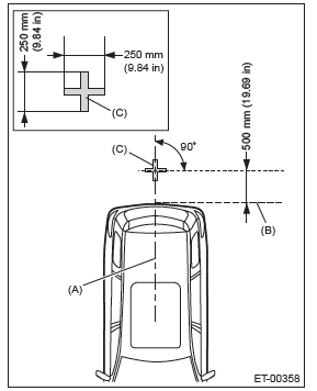
- Vehicle body center line
- Rear edge of bumper
- Target point
3) Confirm the following before checking the corresponding items.
- Navigation
- If the display is blank.
Rearview camera image is not displayed. (Navigation screen is displayed normally.)
- Check the condition of back sensor connection. <Ref. to ET-9, CHECK EACH VEHICLE SIGNAL, INSPECTION, Navigation System.>
- Check the condition of rearview camera connection. <Ref. to ET-8, CHECK EACH CONNECTION, INSPECTION, Navigation System.>
- If the marker is not displayed.
- Check the UART communication. <Ref. to ET-8, CHECK EACH CONNECTION, INSPECTION, Navigation System.>
- If the marker position is not aligned.
- Adjust the marker position according to the MARKER ADJUSTMENT MODE. <Ref. to ET-51, MARKER ADJUSTMENT MODE, ADJUSTMENT, Rearview Camera System.>
- Rearview mirror (RCD model)
- If the rearview camera display is blank.
- Check the condition of back sensor connection. <Ref. to ET-9, CHECK EACH VEHICLE SIGNAL, INSPECTION, Navigation System.>
- Check the condition of rearview camera connection. <Ref. to ET-8, CHECK EACH CONNECTION, INSPECTION, Navigation System.>
- Check the room mirror. <Ref. to GW-62, ADJUSTMENT, Rearview Mirror (RCD Model).>
E: ADJUSTMENT
1. MARKER ADJUSTMENT MODE
Navigation
1) Prepare the target point. <Ref. to ET-50, INSPECTION, Rearview Camera System.>
2) Display the audio OFF screen by turning the ignition switch to ON, then touch the screen in the order of (1) - (6).
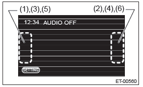
3) When the Dealer Diag menu screen is displayed, touch the "Rear Camera Setup" from the items.
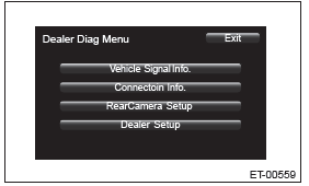
CAUTION: Do not select the item other than "Rear Camera Setup". The navigation system can not operate normally.
4) Shift the select lever to the "R" position to display the image of the rearview camera.
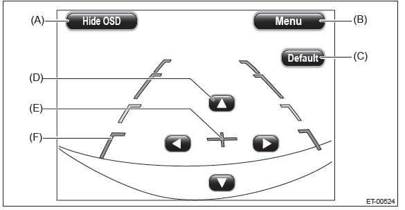
5) Touch the adjustment keys on the display screen to adjust the marker line.
- Sedan model
- OUTBACK model
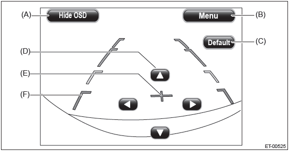
- Hide OSD key
- Menu key
- Default key
- Adjustment keys
- Cross line
- Vehicle width and distance reference line
- Confirm that the target point position in the display screen is identified.
- Adjust by touching the adjustment keys so that the cross line (E) and target point join together.
NOTE:
- Hide OSD key: Touching the Hide OSD key hides the operation keys. When the operation keys are not displayed, touching the display screen displays the operation keys again.
- Menu key: Touching this key shifts to the Dealer Diag Menu screen.
- Default key: Touching this key resets the adjustment values to the default condition.
6) Turn the ignition switch to OFF and wait for 60 seconds or more before turning the ignition switch to ON again.
CAUTION: If the ignition switch is turned to OFF, be sure to wait for 60 seconds or more before turning the ignition switch to ON again.
If turning the ignition switch to ON again or disconnecting the ground cable from battery within 60 seconds after turning the ignition switch to OFF, the navigation unit data updating can not be performed correctly.
7) Shift the select lever to the "R" position to display the image of the rearview camera.
8) Confirm that the marker line position is correctly adjusted before turning the ignition switch to OFF, then finish the procedures.
READ NEXT:
 Front Accessory Power Supply Socket
A: WIRING DIAGRAM
Refer to "Front Accessory Power Supply Socket System" in the wiring diagram.
<Ref. to WI-166, WIRING DIAGRAM,
Front Accessory Power Supply Socket System.>
B: REMOVAL
1) Discon
AUX Input Terminal
A: REMOVAL
1. AUX INPUT TERMINAL
1) Disconnect the ground cable from battery.
2) Remove the console front cover assembly.
MT model
1. Remove the shift knob.
2. Release the clips and claws, then p
Communication System
General Description
A: COMPONENT
Hi pitch side horn
Lo pitch side horn
Roll connector
Horn switch (driver's airbag module
ASSY)
Horn relay
B: CAUTION
Before disassembling or reassembling pa
SEE MORE:
Top tether anchorages
Your vehicle is equipped with three top tether anchorages so that a child restraint
system having a top tether can be installed in the rear seat. When installing a
child restraint system using top tether, proceed as follows, while observing the
instructions by the child restraint system manufa
Side mirrors
After hitching a trailer to your vehicle, check that the standard side mirrors provide a good rearward field of view without significant blind spots. If significant blind spots occur with the vehicle’s standard side mirrors, use towing mirrors that conform with Federal, state/prov
