Subaru Outback (BR): Steering Satellite Switch
A: REMOVAL
CAUTION: Refer to "CAUTION" of "General Description" before handling the airbag module. <Ref. to AB-9, CAUTION, General Description.>
1) Position the front wheels straight ahead. (After moving a vehicle 5 m (16 ft) or more with front wheels positioned straight ahead, make sure that the vehicle moves straight ahead.)
2) Turn the ignition switch to OFF.
3) Disconnect the ground cable from battery and wait for at least 60 seconds before starting work.
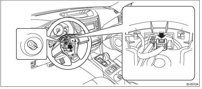
4) Remove the driver's airbag module assembly.
- Using a hexagon wrench etc. wrapped by protective tape, insert the snap pins and release the locks (3 locations).
- Disconnect the horn harness and airbag connector and remove the airbag module assembly. <Ref. to AB-21, DRIVER'S AIRBAG MODULE, CURTAIN AIRBAG MODULE & PRETENSIONER, PROCEDURE, Airbag Connector.>
5) Remove the steering wheel.
CAUTION:
- Always use the steering wheel puller for removal to avoid deforming the steering wheel.
- If the steering wheel has been removed, make sure that the roll connector is not turned from the original position.
- Disconnect the connector and remove the nut.
- Put alignment marks and remove the steering wheel.
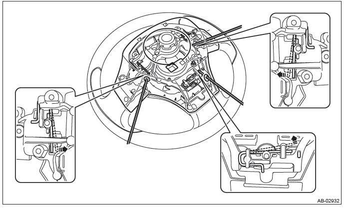
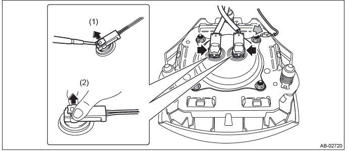
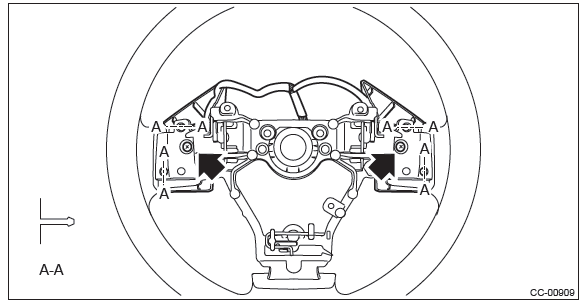
6) Remove the satellite switch.
- Remove the screw, disconnect the connector and remove the paddle shift switch. (Model with paddle shift)
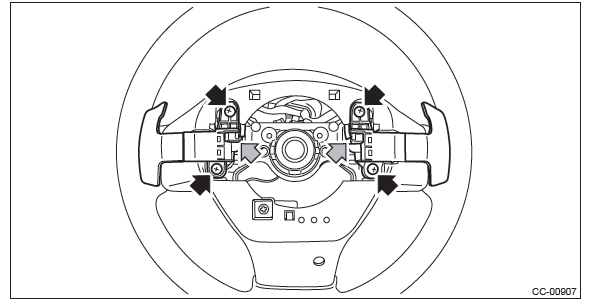
- Release the claws and clips, detach the cover - steering wheel LWR.
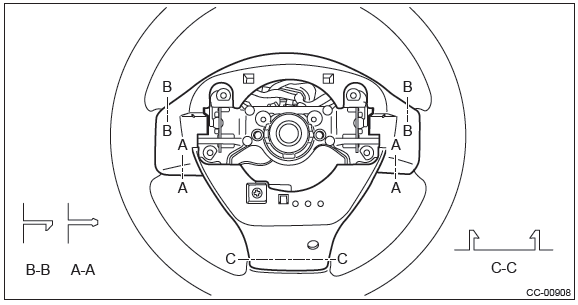
- Remove the screws and then remove the satellite switch assembly.
B: INSTALLATION
Install each part in the reverse order of removal.
Tightening torque:
Steering wheel: 39 N*m (4.0 kgf-m, 28.8 ft-lb)
Clearance:
Between column cover and steering wheel: 2 - 4 mm (0.08 - 0.16 in)
C: INSPECTION
1) Measure the resistance between satellite switch connector terminals.
- Audio operation
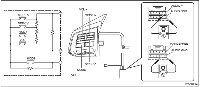
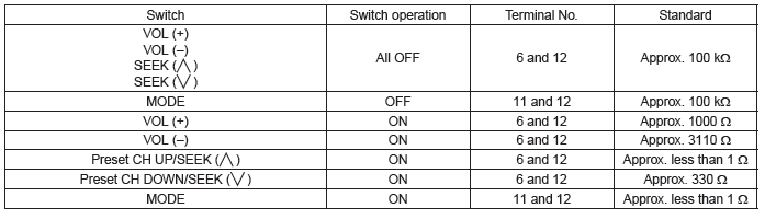
- Handsfree operation
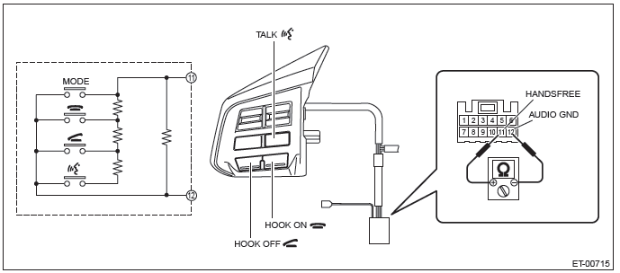
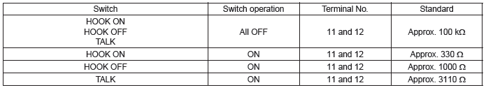
2) If the result of the measurement is not at the standard value, replace the satellite switch.
Navigation Body
A: REMOVAL
CAUTION:
- When replacing the navigation unit, be sure to replace with specified navigation unit. The marker adjustment can not be performed correctly if replacing with unspecified navigation unit.
- After replacing the navigation unit, be sure to check that the rearview camera images and the marker line are displayed.
1) Disconnect the ground cable from battery.
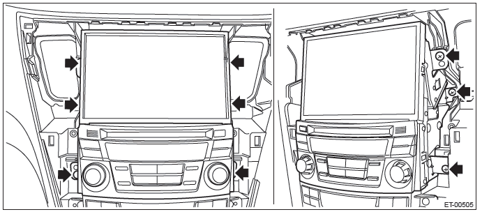
2) Remove the center panel assembly.
CAUTION: Do not put your finger on the fin of the air vent grille. Doing so may damage the fin.
- Attach the protective tape (a) to the meter visor.
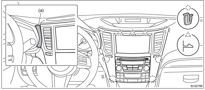
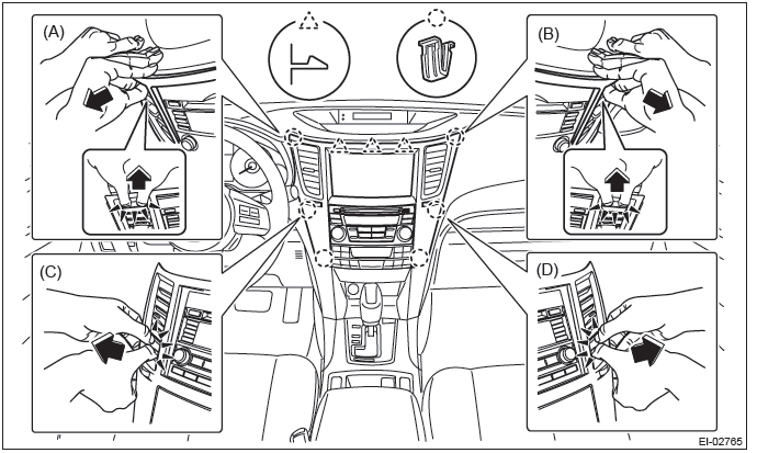
- Insert a finger into the air vent grille and release the left and right
clips at the top of the center panel.
(A), (B)
- Insert a finger into the air vent grille and release the left and right
clips at the center of the center panel.
(C), (D)
- Release the clips at the bottom of the center panel and remove the center panel assembly.
3) Remove the navigation assembly.
- Remove the left and right screws.
- Disconnect the connector and remove the navigation assembly.
B: INSTALLATION
Install each part in the reverse order of removal.
READ NEXT:
 GPS Antenna
A: REMOVAL
1) Disconnect the ground cable from battery.
2) Remove the center panel assembly.
CAUTION:
Do not put your finger on the fin of the air vent grille. Doing so may damage
the fin.
Attach
Rearview Camera System
A: WIRING DIAGRAM
Refer to "Rearview Camera System" in the wiring diagram. <Ref. to WI-213,
WIRING DIAGRAM, Rearview
Camera System.>
B: REMOVAL
1. SEDAN MODEL
1) Disconnect the ground cable fro
Front Accessory Power Supply Socket
A: WIRING DIAGRAM
Refer to "Front Accessory Power Supply Socket System" in the wiring diagram.
<Ref. to WI-166, WIRING DIAGRAM,
Front Accessory Power Supply Socket System.>
B: REMOVAL
1) Discon
SEE MORE:
Loading all the magazine (full disc loading mode)
1. If you continue to press the “LOAD” button for more than 1.5 seconds, the
player will produce beep sound and will enter the full disc loading mode.
2. When the disc number indicator flashes and “ALL LOAD” indicator illuminates,
insert a disc within 15 seconds. If a disc is successf
Cruise Control System (Diagnostics)
Basic Diagnostic Procedure
A: PROCEDURE
CAUTION:
When performing diagnosis, observe the legal speed limit on the road.
The cancel code will be also appear when cruise control is cancelled
by the driver's operation. Do
not confuse them.
Be sure to get an assistant to support the diagnosis whil
