Subaru Outback (BR): Basic Diagnostic Procedure of Continuously Variable Transmission
A: PROCEDURE
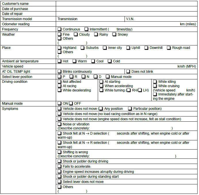
Check List for Interview
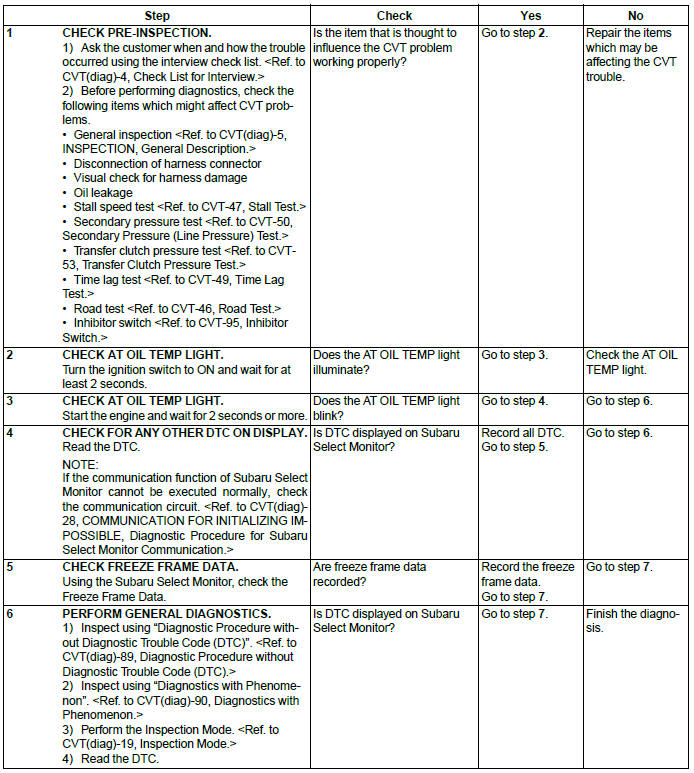
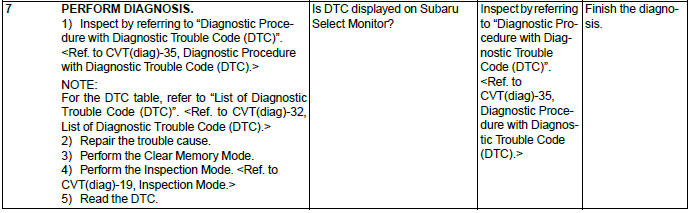
A: CHECK
Check the following items when a problem has occurred.
NOTE: Use copies of this page for interviewing customers.
General Description
A: CAUTION
1. SUPPLEMENTAL RESTRAINT SYSTEM "AIRBAG"
The airbag system wiring harness is routed near the TCM.
CAUTION:
- All the airbag system wiring harnesses and connectors are colored yellow. Do not use an electric test equipment to check these circuits.
- Be careful not to damage the airbag system wiring harness when performing diagnostics or servicing the TCM.
2. MEASUREMENT
When measuring the voltage and resistance of the ECM, TCM or each sensor, use a tapered pin with a diameter of less than 0.64 mm (0.025 in) in order to avoid poor contact. Do not insert a pin of more than 0.65 mm (0.026 in) diameter.
B: INSPECTION
1. BATTERY
Measure the battery voltage and specific gravity of the electrolyte.
Standard voltage: 12 V or more
Specific gravity: 1.260 or more
2. TRANSMISSION GROUND
Make sure that the ground terminal bolt is tightened securely.
Tightening torque: 16 N*m (1.6 kgf-m, 11.8 ft-lb)
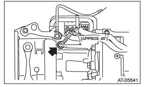
3. OPERATION OF SHIFT SELECT LEVER
Make sure there is no noise, dragging or contact pattern in each select lever range.
WARNING: Stop the engine while checking operation of the select lever.
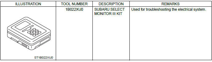
C: PREPARATION TOOL
1. SPECIAL TOOL
2. GENERAL TOOL

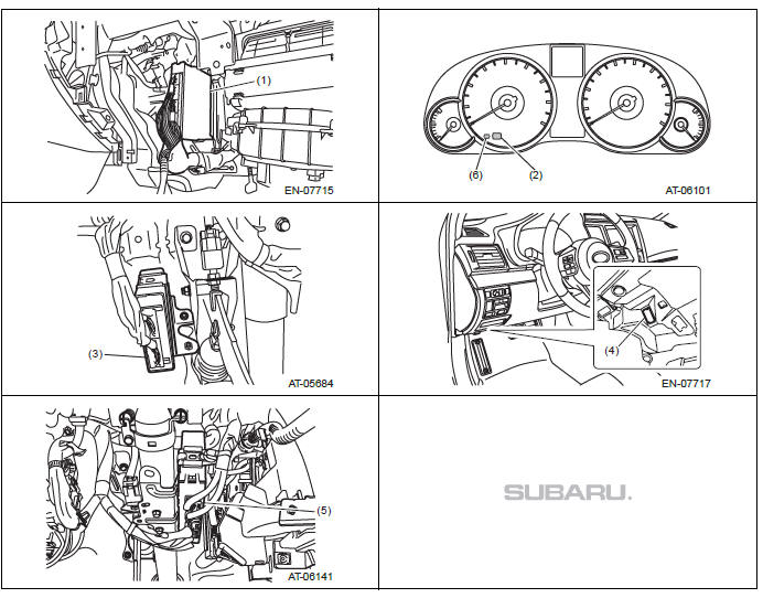
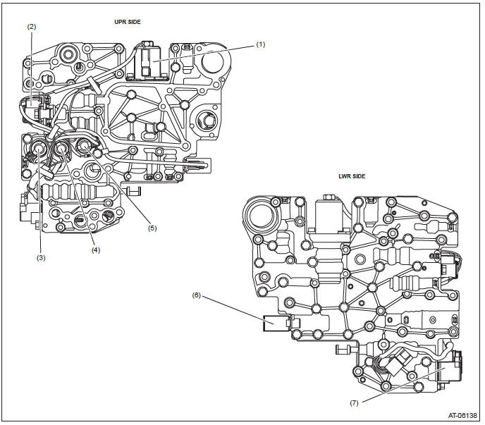
Electrical Component Location
A: LOCATION
1. CONTROL MODULE
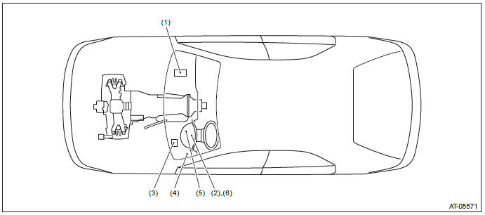
- Engine control module (ECM)
- AT OIL TEMP light
- Transmission control module (TCM)
- Data link connector
- Body integrated unit
- AWD light
2. SENSOR
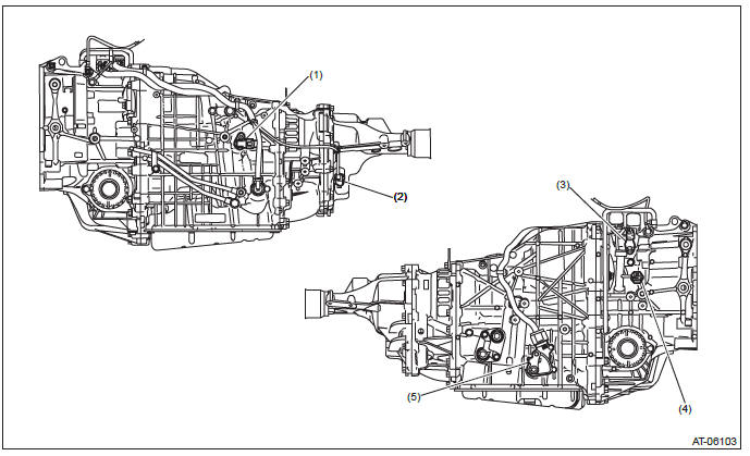
- Secondary speed sensor
- Front wheel speed sensor
- Primary speed sensor
- Secondary pressure sensor
- Inhibitor switch
3. SOLENOID
- Secondary solenoid
- AWD solenoid
- Lock-up duty solenoid
- Primary DOWN solenoid
- Primary UP solenoid
- F&R solenoid
- Lock-up ON/OFF solenoid
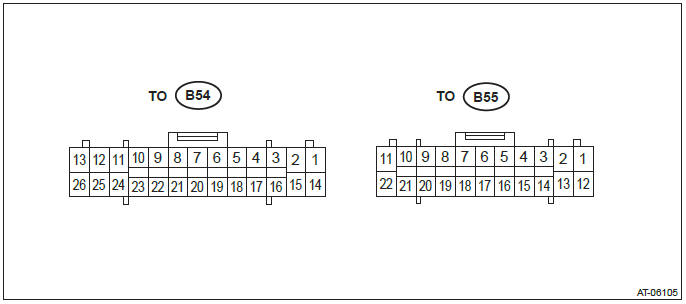
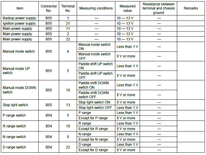
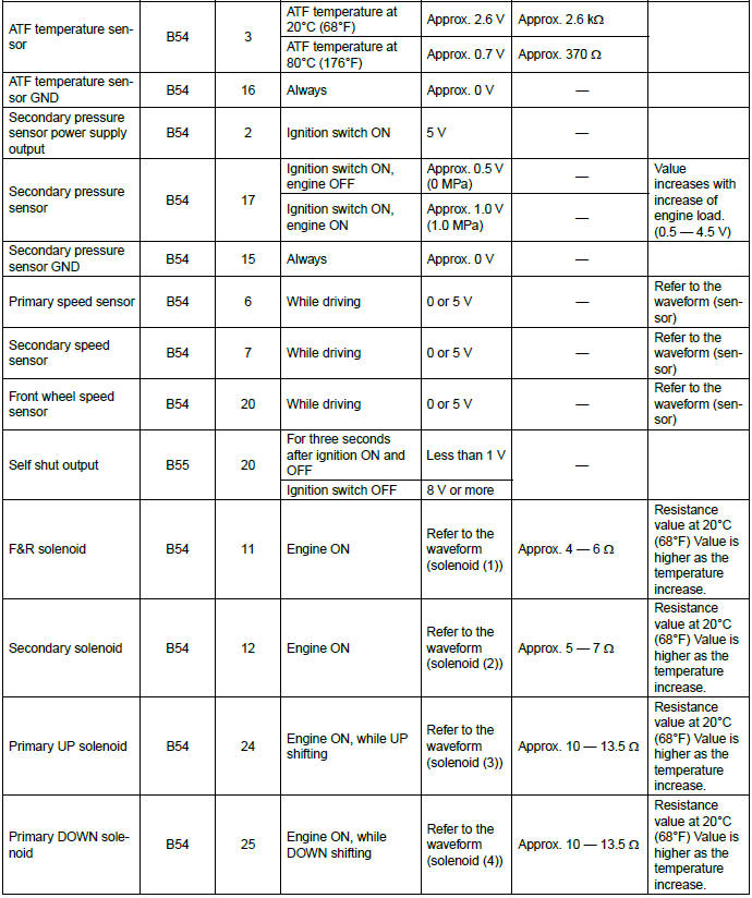
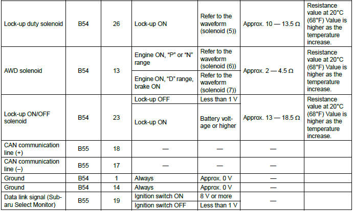
Transmission Control Module (TCM) I/O Signal
A: ELECTRICAL SPECIFICATION
NOTE: Measure after warming up.
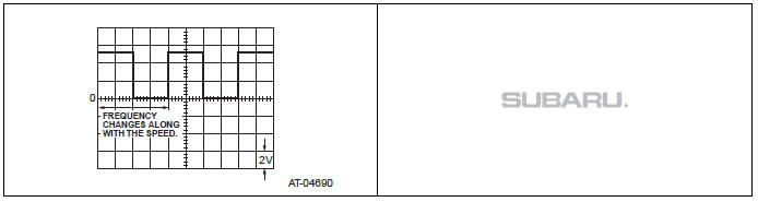
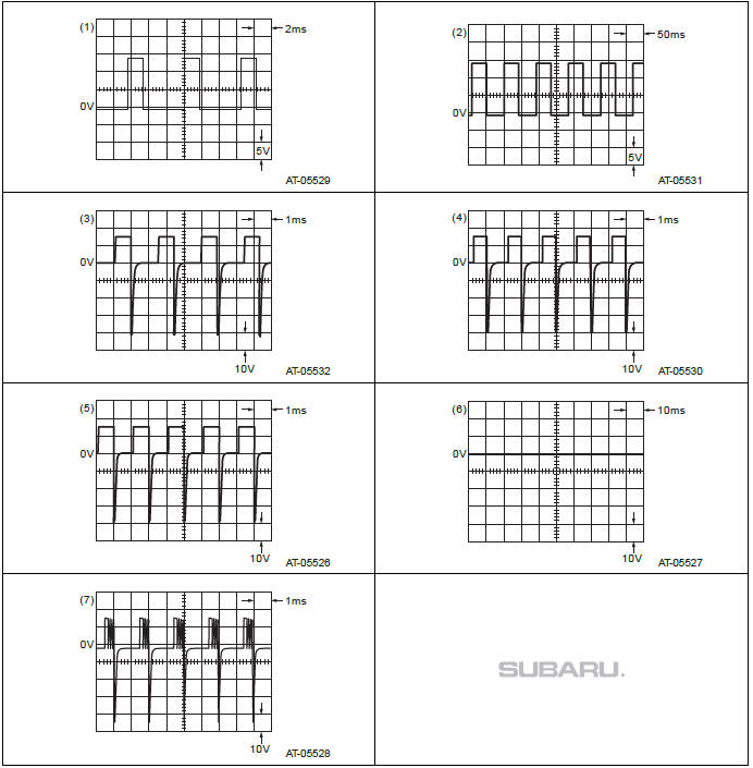
B: WAVEFORM
1. SENSOR
2. SOLENOID
Subaru Select Monitor
A: OPERATION
For detailed operation procedures, refer to "PC application help for Subaru Select Monitor".
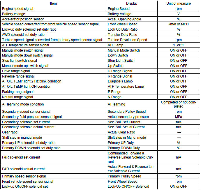
Read Current Data
A: OPERATION
For detailed operation procedures, refer to "PC application help for Subaru Select Monitor".
- The support data list is as follows.
Read Diagnostic Trouble Code (DTC)
A: OPERATION
For detailed operation procedures, refer to "PC application help for Subaru Select Monitor".
NOTE: For details concerning DTC, refer to List of Diagnostic Trouble Code (DTC). <Ref. to CVT(diag)-32, List of Diagnostic Trouble Code (DTC).>
Clear Memory Mode
A: OPERATION
For detailed operation procedures, refer to "PC application help for Subaru Select Monitor".
CAUTION:
- If {Clear Memories 2} is executed, learned control memory are cleared.
- If {Clear Memories 2} is executed, perform learning. <Ref. to CVT(diag)-20, Learning Control.>
Inspection Mode
A: PROCEDURE
<Ref. to CVT-46, Road Test.>
Learning Control
A: GENERAL DESCRIPTION
- Follow the messages displayed on the Subaru Select Monitor when working.
- When the following work is performed, perform learning for the transmission.
Replacement of TCM/Replacement or disassembly of transmission assembly/Replacement of control valve body/Performing "Clear Memories 2".
B: PROCEDURE
1. PREPARATION FOR LEARNING
1) Warm up or cool down until the ATF temperature displayed on the Subaru Select Monitor is 40 - 65ºC (104 - 149ºF).
2) After stopping the vehicle, shift the select lever to "P" range.
3) Apply the electronic parking brake.
4) Lift up the vehicle.
CAUTION: While working, be sure to keep the lower edge of the tires 30 cm or more above the ground as vehicle will vibrate.
5) Connect the Subaru Select Monitor to data link connector.
6) Turn the ignition switch to ON.
7) Turn off all switches causing an electrical load, such as headlights, A/C, seat heater and rear defogger.
2. SIMPLE LEARNING
NOTE: Simple learning is performed with the vehicle lifted, without actually running the vehicle.
CAUTION: Do not turn the power of the Subaru Select Monitor OFF during work, and do not disconnect the data link connector.
1) Select {AT related learning & inspecting mode} in the "Transmission Diagnosis" display screen of the Subaru Select Monitor.
2) Select {AT learning mode} in the "AT related learning & inspecting mode" screen of the Subaru Select Monitor.
3) Follow the messages displayed on the Subaru Select Monitor screen when working.
NOTE: During AT learning in progress, AT OIL TEMP light in the combination meter starts flashing at 2 Hz and the learning operation starts. The following message is displayed on the screen when the AT OIL TEMP light which was flashing at 2 Hz turns off.
4) When "AT learning normally ended." is displayed, simple AT learning is completed.
NOTE:
- If communication error occurs during learning, retry the "AT learning mode" from the beginning.
- If the message "Execute AT learning again after fixing troubles of the vehicle" appears during learning, select [OK] and display the DTC list. After repairing the locations indicated by the DTC, start the "AT learning mode" over from the beginning.
- When communication error occurs during learning, select lever does not shift occasionally. If select lever does not shift, turn the ignition switch to OFF before operating the select lever.
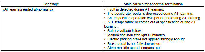
- If the message "AT learning ended abnormally." is displayed, start the "AT learning mode" over from the beginning.
- For detailed operation procedures, refer to "PC application help for Subaru Select Monitor".
AT OIL TEMP Warning Light Display
A: OPERATION
The AT OIL TEMP light illuminates or blinks, when the ATF temperature is high and malfunction occurs in CVT.
- When normal
AT OIL TEMP light always illuminates when the ignition switch is ON (engine OFF). Light goes off after two seconds from engine ON.
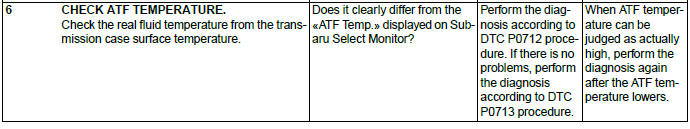
- When ATF temperature is high
AT OIL TEMP light illuminates when the ATF temperature is abnormally high with engine ON.
- When malfunction is detected
AT OIL TEMP light blinks at 2 Hz when the TCM detects the malfunction of CVT with engine ON. In this case, inspect using "Diagnostic Procedure with Diagnostic Trouble Code (DTC)". <Ref. to CVT(diag)-35, Diagnostic Procedure with Diagnostic Trouble Code (DTC).>
- When AT learning is not finished
AT OIL TEMP light repeats "Blinking at 4 Hz → Turning OFF" every two seconds, when the AT learning is not finished with engine ON. In this case, perform the "Learning". (During AT learning, the light blinks at 2 Hz or illuminates.) <Ref. to CVT(diag)-20, Learning Control.>
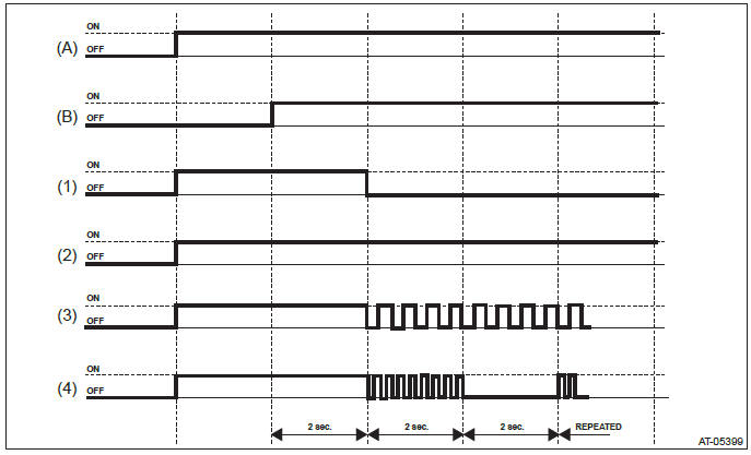
- Ignition switch condition
- Engine condition
- When normal
- When ATF temperature is high
- When malfunction is detected
- When AT learning is not finished
IF the AT OIL TEMP light does not illuminate, or illumination patterns are not as above, check the AT OIL TEMP light circuit. <Ref. to CVT(diag)-23, INSPECTION, AT OIL TEMP Warning Light Display.>
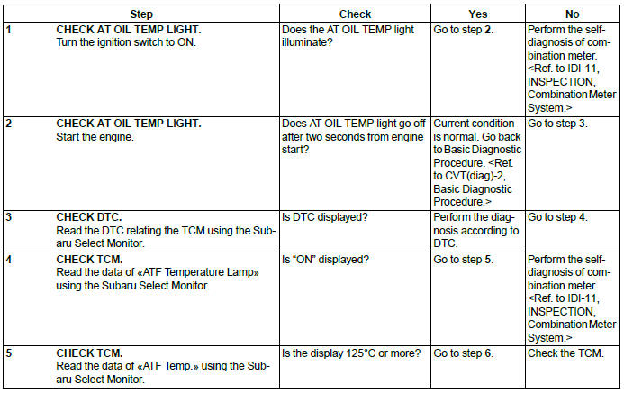
B: INSPECTION
DIAGNOSIS:
- AT OIL TEMP light circuit is open or shorted.
- Combination meter malfunction
- TCM is in special control mode.
- AT learning is not finished.
TROUBLE SYMPTOM:
- When the ignition switch is turned to ON, the AT OIL TEMP light does not illuminate.
- AT OIL TEMP light remains lit after engine start.
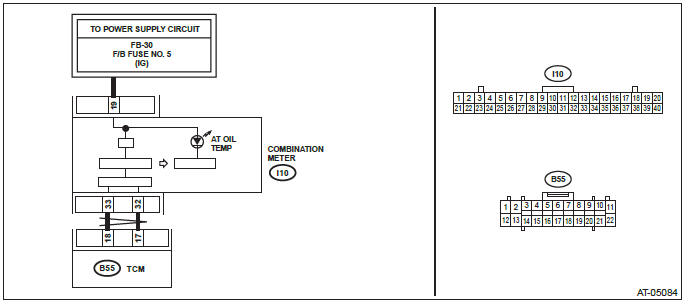
WIRING DIAGRAM:
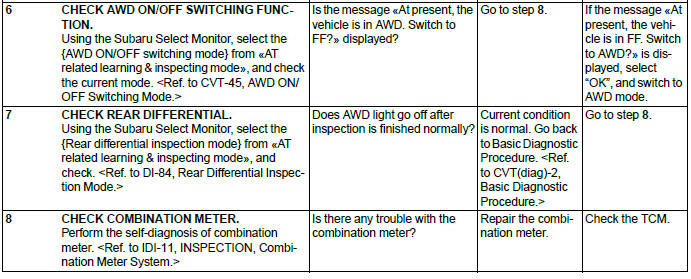
AWD Warning Light Display
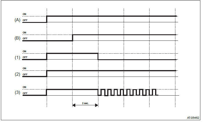
A: OPERATION
AWD light illuminates or blinks, when the AWD is in special control condition and AWD has malfunction.
- When normal
AWD light always illuminates when the ignition switch is ON (engine OFF). Light goes off after two seconds from engine ON.
- When FF mode is selected
AWD light illuminates, when the AWD ON/OFF switching function is "FF mode" with engine ON.
- When malfunction is detected
AWD light blinks at 2 Hz when any of following malfunctions are detected with engine ON.
- When tire with different diameter is installed, or air pressure of any of four wheels is excessively low
- When "Rear differential inspection mode" is judged as NG <Ref. to DI-84, Rear Differential Inspection Mode.>
- Ignition switch condition
- Engine condition
- When normal
- When FF mode is selected
- When malfunction is detected
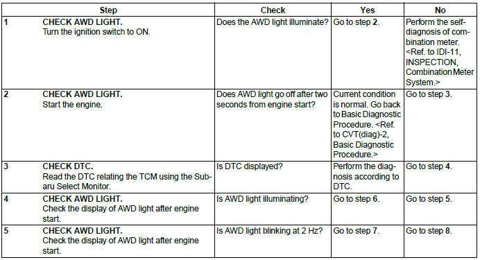
If the AWD light does not illuminate, or illumination patterns are not as above, check the AWD light circuit.
<Ref. to CVT(diag)-26, INSPECTION, AWD Warning Light Display.>
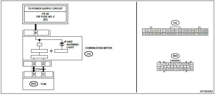
B: INSPECTION
DIAGNOSIS:
- AWD light circuit is open or shorted.
- Combination meter malfunction
- TCM is in AWD special control mode.
TROUBLE SYMPTOM:
- When the ignition switch is turned to ON, the AWD light does not illuminate.
- AWD light remains lit after engine start.
- AWD light is blinking immediately after engine start.
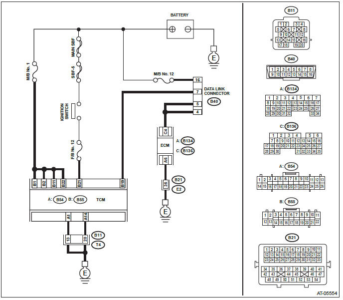
WIRING DIAGRAM:
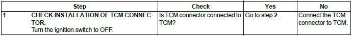
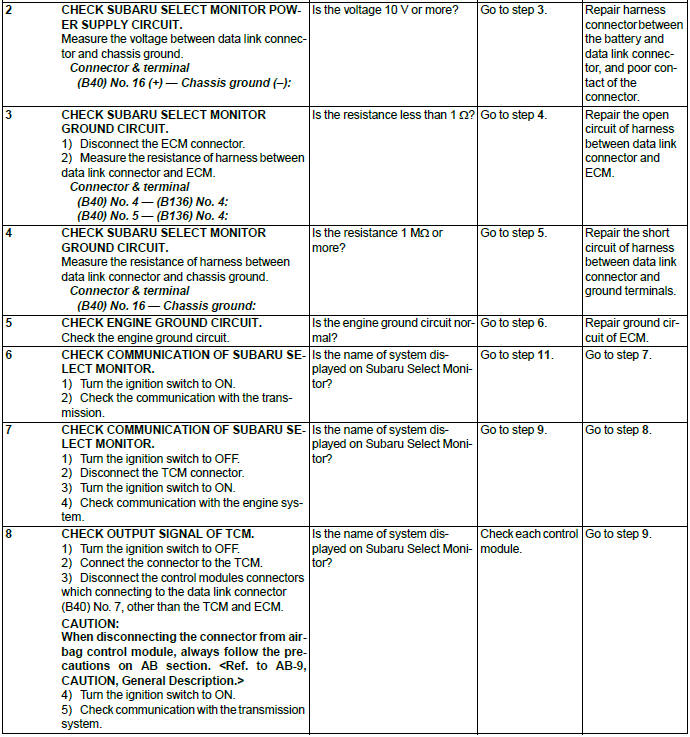
Diagnostic Procedure for Subaru Select Monitor Communication
A: COMMUNICATION FOR INITIALIZING IMPOSSIBLE
DIAGNOSIS:
Defective harness connector
TROUBLE SYMPTOM:
Subaru Select Monitor communication failure
WIRING DIAGRAM:
READ NEXT:
 Continuously Variable Transmission - List of Diagnostic Trouble Code (DTC)
A: LIST
Diagnostic Procedure with Diagnostic Trouble Code (DTC)
A: DTC P0705 TRANSMISSION RANGE SENSOR CIRCUIT (PRNDL INPUT)
DTC DETECTING CONDITION:
Inhibitor switch is faulty.
A
General Description of Automatic Transmission
A: SPECIFICATION
1. TORQUE CONVERTER CLUTCH
2. OIL PUMP
3. TRANSMISSION CONTROL ELEMENT
4. TRANSMISSION GEAR RATIO
5. PLANETARY GEAR AND PLATE
6. SELECTOR POSITION
7. HYDRAULIC CONT
SEE MORE:
Preparing to drive
You should perform the following checks and adjustments every day before you
start driving.
1. Check that all windows, mirrors, and lights are clean and unobstructed.
2. Check the appearance and condition of the tires. Also check tires for proper
inflation.
3. Look under the vehicle for any s
Windows
WARNING
To avoid serious personal injury caused by entrapment, always conform to the
following instructions without exception.
● When operating the power windows, be extremely careful to prevent anyone’s
fingers, arms, neck, head or other objects from being caught in the window.
χ
