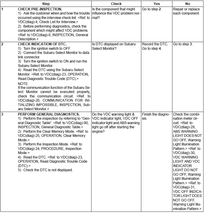
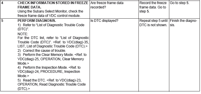
Subaru Outback (BR): Basic Diagnostic Procedure of Vehicle Dynamics Control
A: PROCEDURE
CAUTION: Remove foreign matter (dust, water, oil etc.) from the VDCCM&H/U connector during removal and installation.
NOTE:
- To check the harness for open or short circuits, shake problem spot or connector.
- Refer to "Check List for Interview". <Ref. to VDC(diag)-4, Check List for Interview.>
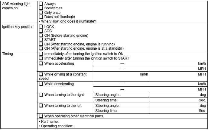
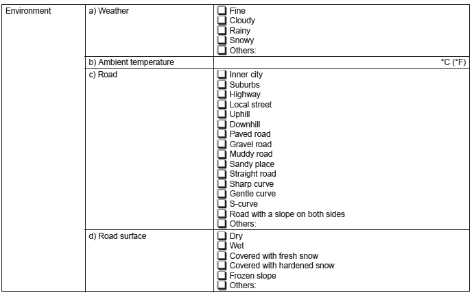
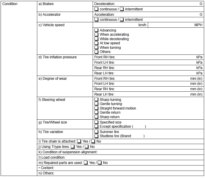
Check List for Interview
A: CHECK
Check the following item about the vehicle's state.
1. STATE OF ABS WARNING LIGHT
2. STATE OF VDC WARNING LIGHT & VDC INDICATOR LIGHT

3. STATE OF VDC OFF INDICATOR LIGHT
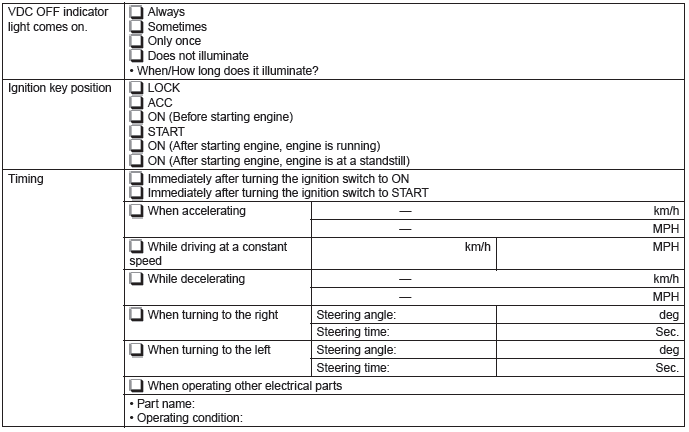
4. CONDITIONS UNDER WHICH TROUBLE OCCURS
General Description
A: CAUTION
1. SUPPLEMENTAL RESTRAINT SYSTEM "AIRBAG"
Airbag system wiring harness is routed near the ABS wheel speed sensor and VDCCM&H/U.
CAUTION:
- Do not use electrical test devices on airbag system wiring harnesses or connector circuits.
- Be careful not to damage the airbag system wiring harness when servicing the ABS wheel speed sensor and VDCCM&H/U.
B: INSPECTION
Before performing diagnosis, check the following items which might affect VDC problems.
1. BATTERY
Measure the battery voltage and check electrolyte.
Standard voltage: 12 V or more
Specific gravity: 1.260 or more
2. GROUND
Check the tightening torque of ground (GV) bolt for VDC.
Tightening torque: 13 N*m (1.3 kgf-m, 9.6 ft-lb)
3. BRAKE FLUID
1) Check the brake fluid level.
2) Check the brake fluid for leaks.
4. HYDRAULIC UNIT
Check the hydraulic unit.
- With brake tester <Ref. to VDC-12, CHECKING THE HYDRAULIC UNIT ABS OPERATION WITH THE BRAKE TESTER, INSPECTION, VDC Control Module and Hydraulic Control Unit (VDCCM& H/U).>
- Without brake tester <Ref. to VDC-12, CHECKING THE HYDRAULIC UNIT ABS OPERATION BY PRESSURE GAUGE, INSPECTION, VDC Control Module and Hydraulic Control Unit (VDCCM& H/U).>
5. BRAKE DRAG
Check for brake drag.
6. BRAKE PAD AND ROTOR
Check the brake pad and rotor.
- Front <Ref. to BR-17, INSPECTION, Front Brake Pad.> <Ref. to BR-19, INSPECTION, Front Disc Rotor.>
- Rear <Ref. to BR-31, INSPECTION, Rear Brake Pad.> <Ref. to BR-34, INSPECTION, Rear Disc Rotor.>
7. TIRE
Check the tire specifications, tire wear and air pressure.
<Ref. to WT-2, SPECIFICATION, General Description.>
C: PREPARATION TOOL
1. SPECIAL TOOL
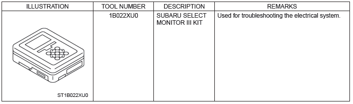
2. GENERAL TOOL

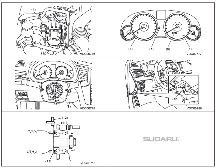
Electrical Component Location
A: LOCATION
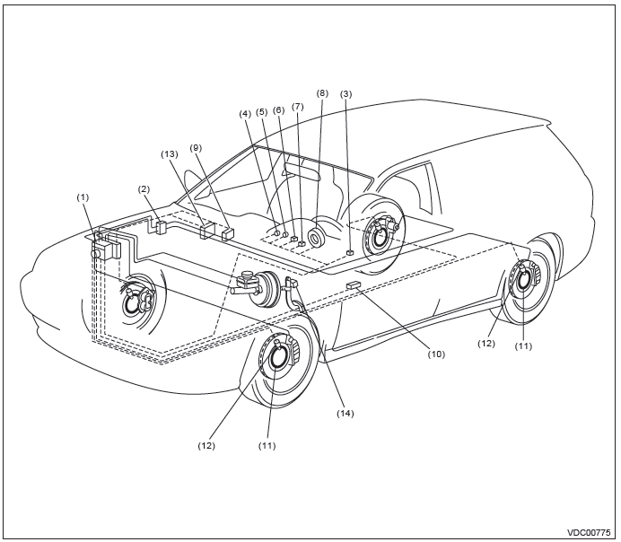
- VDC control module & hydraulic control unit (VDCCM&H/U)
- Connector
- VDC OFF switch
- ABS warning light
- Brake warning light (EBD warning light)
- VDC warning light & VDC indicator light
- VDC OFF indicator light
- Steering angle sensor
- Transmission control module (TCM)
- Data link connector
- Magnetic encoder
- ABS wheel speed sensor
- Engine control module (ECM)
- Stop light & brake switch
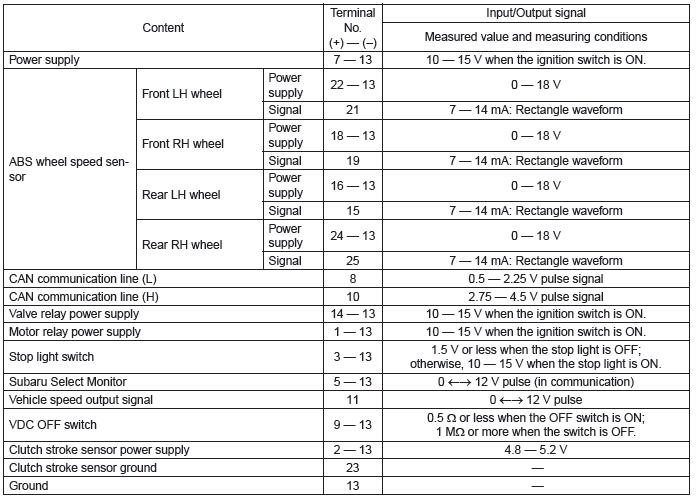
Control Module I/O Signal
A: ELECTRICAL SPECIFICATION
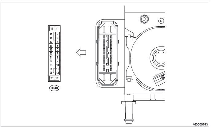
NOTE:
- Terminal numbers in VDCCM&H/U connector are shown in the figure.
- When the connector is removed from VDCCM&H/U, the brake warning light (EBD warning light), ABS warning light, and VDC warning light & VDC indicator light illuminate.
B: WIRING DIAGRAM
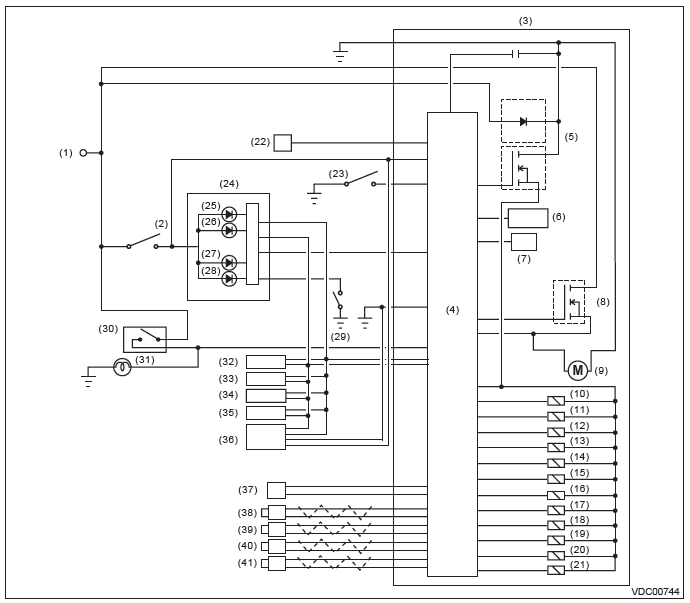
- Battery
- Ignition switch
- VDC control module & hydraulic control unit (VDCCM&H/U)
- VDC control module
- Valve relay
- Pressure sensor
- Yaw rate & G sensor
- Motor relay
- Motor
- Front inlet solenoid valve LH
- Front outlet solenoid valve LH
- Front inlet solenoid valve RH
- Front outlet solenoid valve RH
- Rear inlet solenoid valve LH
- Rear outlet solenoid valve LH
- Rear inlet solenoid valve RH
- Rear outlet solenoid valve RH
- Primary cut solenoid valve
- Primary suction solenoid valve
- Secondary cut solenoid valve
- Secondary suction solenoid valve
- Data link connector
- VDC OFF switch
- Combination meter
- VDC OFF indicator light
- VDC warning light & VDC indicator light
- ABS warning light
- Brake warning light (EBD warning light)
- Brake fluid level switch
- Stop light switch
- Stop light
- Body integrated unit
- Engine control module (ECM)
- Transmission control module (TCM)
- Parking brake control module
- Steering angle sensor
- Clutch stroke sensor (MT model only)
- Front ABS wheel speed sensor LH
- Front ABS wheel speed sensor RH
- Rear ABS wheel speed sensor LH
- Rear ABS wheel speed sensor RH
READ NEXT:
 Subaru Select Monitor
A: OPERATION
1. HOW TO USE SUBARU SELECT MONITOR
NOTE:
For detailed operation procedures, refer to "PC
application help for Subaru Select Monitor".
If VDC and Subaru Select Monitor cannot communic
Warning Light Illumination Pattern
A: INSPECTION
Ignition switch
OFF
ON
Engine start
ABS warning light
Light OFF
Light ON
2 sec.
VDC OFF indicator light
VDC warning light & VDC indicator
light
Several seconds (dependi
Vehicle Dynamics Control - List of Diagnostic Trouble Code (DTC)
A: LIST
Diagnostic Procedure with Diagnostic Trouble Code (DTC)
A: DTC C0021 FRONT RIGHT ABS SENSOR CIRCUIT OPEN OR SHORT
NOTE: For the diagnostic procedure, refer to "DTC C0027 REAR L
SEE MORE:
Understanding the ABS Warning Light in Your Subaru Outback (BR)
ABS warning light serves as an essential indicator of the Anti-Lock Braking System's operational status in your Subaru Outback (BR). When you turn the ignition switch to the “ON” position, the ABS warning light illuminates briefly for approximately 2 seconds, demonstrating that
Continuously Variable Transmission Control Device
A: REMOVAL
1) Remove the transmission assembly from vehicle body. <Ref. to CVT-55, REMOVAL, Automatic Transmission Assembly.>
2) Remove the oil pan and control valve body. <Ref. to CVT-111, REMOVAL, Control Valve Body.>
3) Remove the inhibitor switch. <Ref. to CVT-98, REMOVAL, In
