Subaru Outback (BR): General Description of Transmission Control Systems
Subaru Outback (BR) 2010-2015 Service Manual / Transmission / Control Systems / General Description of Transmission Control Systems
A: COMPONENT
1. AT SELECT LEVER
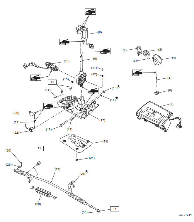
- Cover grip AT
- Button ASSY-AT
- Clamp grip pin
- Grip ASSY sub
- Rod COMPL
- Cover grip AT
- Indicator ASSY
- Arm ASSY
- Selector lever COMPL
- Plate guide
- Rod detent
- Detent spring
- Clamp push nut
- Clamp push nut
- Clamp pin
- Spacer pin guide
- Plate COMPL
- Shaft control
- Spacer pin guide
- Rod shift lock
- Cushion solenoid
- Solenoid unit
- Gasket
- Spacer plate
- Snap pin
- Washer
- Select cable (AT model)
- Select cable (CVT model)
- Clamp
- Nut
Tightening torque: N*m (kgf-m, ft-lb)
T1: 7.5 (0.8, 5.5)
T2: 18 (1.8, 13.3)
2. 6MT GEAR SHIFT LEVER
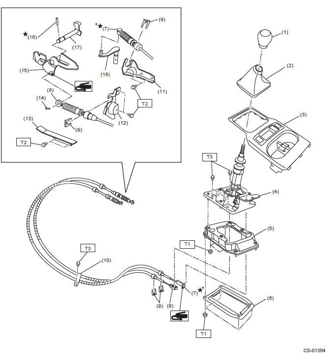
- Shift knob
- Shift boot
- Console front cover ASSY
- Gear shift lever ASSY
- Cover cable ASSY
- Plate cable ASSY
- MT gear select cable (identification tape color: green)
- MT gear shift cable (identification tape color: yellow)
- Clamp
- Clamp cable
- Select bracket
- Shift bracket
- Dust cover
- Snap pin
- Shift lever COMPL
- Spring pin
- Shifter arm No. 2
- Selector lever
Tightening torque: N*m (kgf-m, ft-lb)
T1: 7.5 (0.8, 5.5)
T2: 15 (1.5, 11.1)
T3: 18 (1.8, 13.3)
*: Always use new MT gear select cable if the cable is removed from select lever COMPL of transmission side.
B: CAUTION
- Wear appropriate work clothing, including a cap, protective goggles and protective shoes when performing any work.
- Remove contamination including dirt and corrosion before removal, installation or disassembly.
- Keep the disassembled parts in order and protect them from dust and dirt.
- Before removal, installation or disassembly, be sure to clarify the failure. Avoid unnecessary removal, installation, disassembly and replacement.
- Use SUBARU genuine fluid, grease or equivalent. Do not mix fluid and grease of different grades or manufacturers.
- Be sure to tighten fasteners including bolts and nuts to the specified torque.
- Place shop jacks or rigid racks at the specified points.
- Apply grease onto sliding or revolving surfaces before installation.
- Before installing the O-ring or snap ring, apply a sufficient amount of fluid to avoid damage and deformation.
- Before securing a part in a vise, place cushioning material such as wood blocks, aluminum plate or cloth between the part and the vise.
- Before disconnecting electrical connectors, be sure to disconnect the negative terminal from battery.
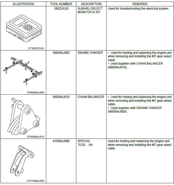
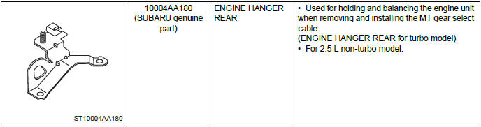
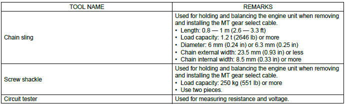
C: PREPARATION TOOL
1. SPECIAL TOOL
2. GENERAL TOOL
READ NEXT:
 AT Shift Lock Control System
A: LOCATION
TCM ("P" range)
Body integrated unit
Stop light switch
Key cylinder (with built-in key
warning switch)
Solenoid unit
"P" range switch
Key lock solenoid
B: ELECTRICAL SPECIFICAT
Select Lever (removal, installation, disassembly, inspection)
A: REMOVAL
1) Shift the select lever to "N" range.
2) Disconnect the ground cable from battery.
3) Lift up the vehicle.
4) Remove the rear exhaust pipe.
2.5 L non-turbo model <
Select Cable
A: REMOVAL
1) Shift the select lever to "N" range.
2) Disconnect the ground cable from battery.
3) Lift up the vehicle.
4) Remove the front exhaust pipe and rear exhaust pipe.
2.5 L model
<Re
SEE MORE:
Installing forward facing child restraint
1. Place the child restraint system in the rear seating position.
2. Run the lap and shoulder belt through or around the child restraint system
following the instructions provided by its manufacturer.
3. Insert the tongue plate into the buckle until you hear a click.
4. Take up the slack in
DTC P0442, P0447, P0448, P0451, P0452, P0453, P0456, P0457, P0458, P0459,
P0461, P0462, P0463, P0464
BV:DTC P0442 EVAPORATIVE EMISSION CONTROL SYSTEM LEAK DETECTED
(SMALL LEAK)
1. OUTLINE OF DIAGNOSIS
The evaporative system monitor detects leak up to 0.020 inch in the fuel tank
and evaporative emissions system.
If the fuel cap is not present or has not been correctly tightened after a
refueling
© 2010-2026 Copyright www.suoutback.com
