Subaru Outback (BR): Select Cable
A: REMOVAL
1) Shift the select lever to "N" range.
2) Disconnect the ground cable from battery.
3) Lift up the vehicle.
4) Remove the front exhaust pipe and rear exhaust pipe.
- 2.5 L model <Ref. to EX(H4SO)-5, REMOVAL, Front Exhaust Pipe.> <Ref. to EX(H4SO)-9, REMOVAL, Rear Exhaust Pipe.>
- 3.6 L model <Ref. to EX(H6DO)-5, REMOVAL, Front Exhaust Pipe.> <Ref. to EX(H6DO)-8, REMOVAL, Rear Exhaust Pipe.>
5) Remove the heat shield cover.
6) Remove the snap pin and washer from the shifter arm and remove the select cable from the shifter arm.
- CVT model
- Shifter arm
- Snap pin
- Select cable
- Plate ASSY
- Washer
- AT model
- Shifter arm
- Snap pin
- Select cable
- Plate ASSY
- Washer
7) Remove the plate assembly from the transmission case.
- CVT model
- Select cable
- Plate ASSY
- AT model
- Select cable
- Plate ASSY
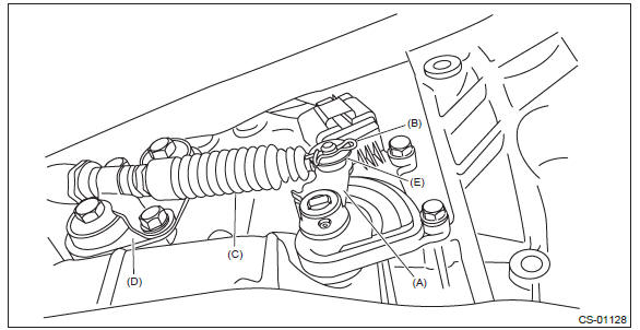
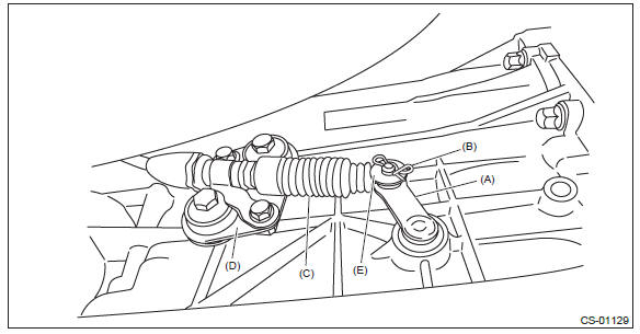
8) Disconnect the cable from arm assembly.
- Nut
- Arm ASSY
9) Raise the claw of clamp to remove the cable from bracket.
- Claw
10) Remove the select cable from plate assembly.
B: INSTALLATION
1) Install the select cable to plate assembly.
Tightening torque: 18 N*m (1.8 kgf-m, 13.3 ft-lb)
2) Install the select cable to range select lever.
3) Install the plate assembly to transmission.
Tightening torque: T: 25 N*m (2.5 kgf-m, 18.4 ft-lb)
- CVT model
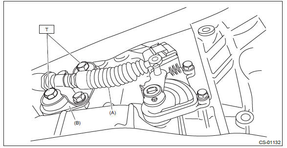
- Select cable
- Plate ASSY
- AT model
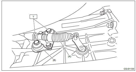
- Select cable
- Plate ASSY
4) Install the washer and snap pin to the shifter arm.
- CVT model
- Shifter arm
- Snap pin
- Select cable
- Plate ASSY
- Washer
- AT model
- Shifter arm
- Snap pin
- Select cable
- Plate ASSY
- Washer
5) Install new clamp paying attention to the installing direction.
- Clamp
- Forward
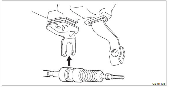
6) Insert the tip of inner cable into connector hole of select lever, and fix the cable to bracket.
7) Shift the select lever to the "N" range, and then adjust the select cable position. <Ref. to CS-50, ADJUSTMENT, Select Cable.>
8) Install the heat shield cover.
Tightening torque: 18 N*m (1.8 kgf-m, 13.3 ft-lb)
9) Install the front exhaust pipe and rear exhaust pipe.
- 2.5 L model <Ref. to EX(H4SO)-6, INSTALLATION, Front Exhaust Pipe.> <Ref. to EX(H4SO)-9, INSTALLATION, Rear Exhaust Pipe.>
- 3.6 L model <Ref. to EX(H6DO)-6, INSTALLATION, Front Exhaust Pipe.> <Ref. to EX(H6DO)-8, INSTALLATION, Rear Exhaust Pipe.>
C: INSPECTION
Check the removed cable and replace or adjust if damaged, rusty or malfunctioning.
1) Check that the inner cable moves smoothly without drag.
2) Check the inner cable for damage and rust.
3) Check the outer cable for damage, bends and cracks.
4) Check the boot for damage, cracks and deterioration.
5) Shift the select lever from "P" range to "D" range. Check the existence of feel to contact the detents in each range. If the detents cannot be felt or the position pointer is improperly aligned, adjust the cable.
6) Check that the starter motor rotates when the select lever is set to "P" or "N" range.
7) Check the back-up light illumination when the select lever is in "R" range.
8) Check the shift lock operation when the select lever is in "P" range.
D: ADJUSTMENT
1) Shift the select lever to "N" range.
2) Lift up the vehicle.
3) Remove the front exhaust pipe and rear exhaust pipe.
- 2.5 L non-turbo model <Ref. to EX(H4SO)-5, REMOVAL, Front Exhaust Pipe.> <Ref. to EX(H4SO)-9, REMOVAL, Rear Exhaust Pipe.>
- 3.6 L model <Ref. to EX(H6DO)-5, REMOVAL, Front Exhaust Pipe.> <Ref. to EX(H6DO)-8, REMOVAL, Rear Exhaust Pipe.>
4) Remove the heat shield cover.
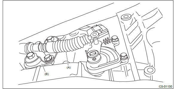
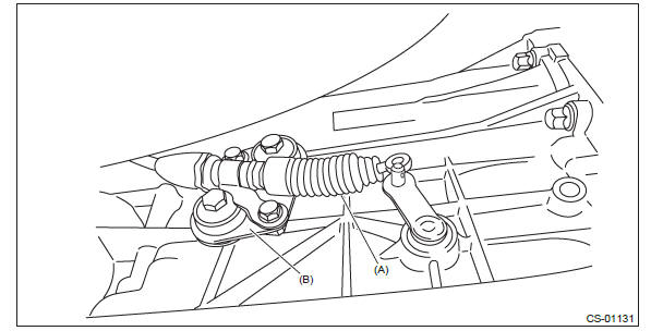
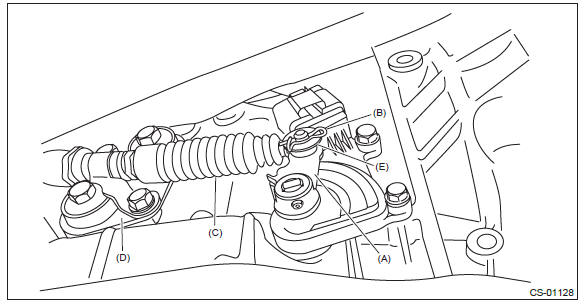
5) Loosen the nuts on both sides.
- Nut A
- Nut B
6) Turn the nut B until it lightly touches the connector.
- Forward side
- Select lever
- Connector
- Nut B
- Contact point
- Nut A
7) Set a spanner wrench to the nut B so that it does not rotate, and then tighten the nut A.
Tightening torque: 7.5 N*m (0.8 kgf-m, 5.5 ft-lb)
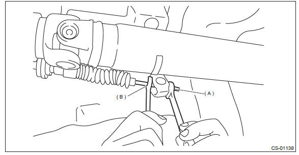
- Nut A
- Nut B
8) After the completion of adjustment, confirm that the select lever operates normally at all ranges.
9) Install in the reverse order of removal.
AT Shift Lock Solenoid and "P" Range Switch
A: REMOVAL
1. SOLENOID UNIT
1) Remove the AT select lever. <Ref. to CS-22, REMOVAL, Select Lever.>
2) Remove the spacer and gasket. <Ref. to CS-31, DISASSEMBLY, Select Lever.>
3) Using a flat tip screwdriver with a thin tip, remove the harness connector from the plate COMPL.
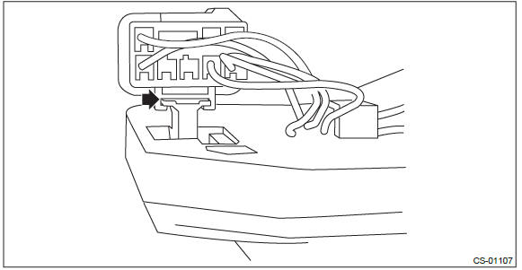
4) Raise the claw using a flat tip screwdriver with a thin tip, and remove the solenoid unit from the plate COMPL.
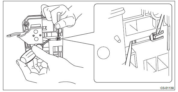
5) Using a flat tip screwdriver with a thin tip, remove the solenoid unit terminals from the harness connector.
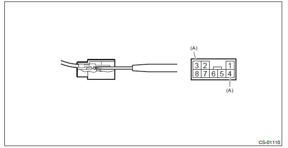
- Solenoid unit terminals
2. "P" RANGE SWITCH
For the removal of "P" range switch, refer to the procedure for AT select lever. <Ref. to CS-31, DISASSEMBLY, Select Lever.>
<Ref. to CS-32, AT SELECT LEVER ASSEMBLY, DISASSEMBLY, Select Lever.>
B: INSTALLATION
Install in the reverse order of removal.
NOTE: Insert the solenoid unit terminals to the harness connector.
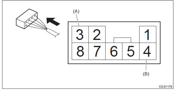
- Solenoid unit (color code: blue)
- Solenoid unit (color code: black)
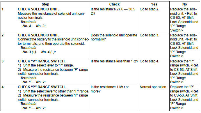
C: INSPECTION
Body Integrated Unit
A: NOTE
Refer to "Body Integrated Unit" for removal and installation procedure. <Ref. to SL-71, Body Integrated Unit.>
READ NEXT:
 MT Gear Shift Lever
A: REMOVAL
1) Disconnect the ground cable from battery.
2) Lift up the vehicle.
3) Remove the center exhaust pipe and rear exhaust pipe. (non-turbo model) <Ref.
to EX(H4SO)-8, REMOVAL,
Center Ex
MT Gear Shift Cable
A: REMOVAL
1) Disconnect the ground cable from battery.
2) Lift up the vehicle.
3) Remove the center exhaust pipe and rear exhaust pipe. (non-turbo model) <Ref.
to EX(H4SO)-8, REMOVAL,
Center Ex
MT Gear Select Cable
A: REMOVAL
CAUTION:
Always use new MT gear select cable if the cable is removed from selector lever
COMPL of transmission
side.
1) Disconnect the ground cable from battery.
2) Remove the ten clips
SEE MORE:
Differential Gear Oil replacement
A: INSPECTION
1) Remove the filler plug, and then check the gear oil. Replace the gear oil if it is contaminated, deteriorated or cloudy. <Ref. to DI-23, REPLACEMENT, Differential Gear Oil.>
2) Check that the gear oil level is within -5 mm (- 0.2 in) from the bottom of the filler plug hole.
Side Airbag Module
A: REMOVAL
CAUTION:
Refer to "CAUTION" of "General Description" before handling the airbag module.
<Ref. to AB-9,
CAUTION, General Description.>
NOTE:
Remove the passenger's side by referring to driver's side.
1) Remove the headrest.
NOTE:
For models with headrest monitor, remove the headrest
