Subaru Outback (BR): Emission Control (Aux. Emission Control Devices)
General Description
A: CAUTION
- Wear appropriate work clothing, including a cap, protective goggles and protective shoes when performing any work.
- Remove contamination including dirt and corrosion before removal, installation or disassembly.
- Keep the disassembled parts in order and protect them from dust and dirt.
- Before removal, installation or disassembly, be sure to clarify the failure. Avoid unnecessary removal, installation, disassembly and replacement.
- Vehicle components are extremely hot after driving. Be wary of receiving burns from heated parts.
- Be sure to tighten fasteners including bolts and nuts to the specified torque.
- Place shop jacks or rigid racks at the specified points.
- Before disconnecting connectors of sensors or units, be sure to disconnect the ground cable from battery.
B: PREPARATION TOOL
1. SPECIAL TOOL
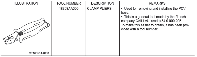
2. GENERAL TOOL

Front Catalytic Converter
A: REMOVAL
The front catalytic converter is integrated into the front exhaust pipe; therefore, refer to "Front Exhaust Pipe" for the removal procedure. <Ref. to EX(H4SO)-5, REMOVAL, Front Exhaust Pipe.>
B: INSTALLATION
The front catalytic converter is integrated into the front exhaust pipe; therefore, refer to "Front Exhaust Pipe" for the installation procedure. <Ref. to EX(H4SO)-6, INSTALLATION, Front Exhaust Pipe.>
C: INSPECTION
1) Check the connections and welds for exhaust leaks.
2) Check for hole or rust.
Rear Catalytic Converter
A: REMOVAL
The rear catalytic converter is integrated into the center exhaust pipe. Refer to "Center Exhaust Pipe" for removal procedures. <Ref. to EX(H4SO)- 8, REMOVAL, Center Exhaust Pipe.>
B: INSTALLATION
The rear catalytic converter is integrated into the center exhaust pipe. Refer to "Center Exhaust Pipe" for installation procedures. <Ref. to EX(H4SO)-8, INSTALLATION, Center Exhaust Pipe.>
C: INSPECTION
1) Check the connections and welds for exhaust leaks.
2) Check for hole or rust.
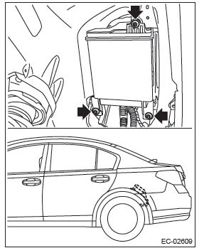
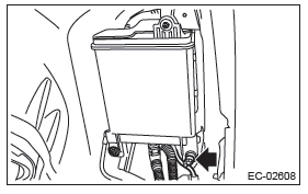
Canister
REMOVAL
1) Remove the rear wheel LH.
2) Lift up the vehicle.
3) Remove the rear mud guard LH. <Ref. to EI-38, REMOVAL, Mud Guard.>
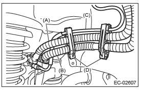
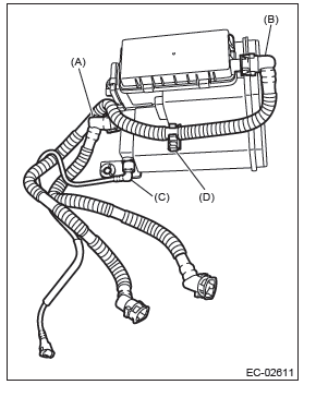
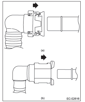
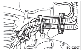
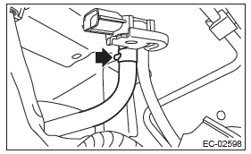
4) Disconnect the quick connectors of the vent tube (A), canister drain tube (B) and charge tube (C), and remove the tubes from tube clamp (D).
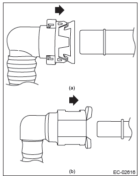
NOTE: Disconnect the quick connector as shown in the figure.
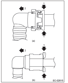
- Vent tube (A) and canister drain tube (B)
- Charge tube (C)
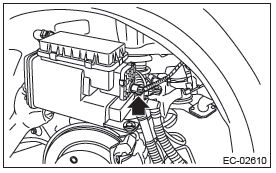
5) Remove the clip holding the rear wiring harness.
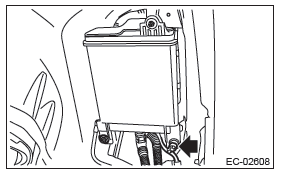
6) Remove the canister from vehicle.
7) Disconnect the connector from drain valve.
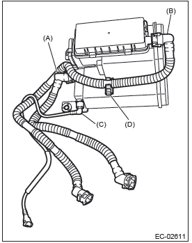
8) Disconnect the vent tube (A), canister drain tube (B) and charge tube (C) from the canister, and remove the canister drain tube (B) from canister clip (D).
NOTE: Disconnect the quick connector as shown in the figure.
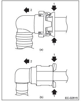
- Vent tube (A) and canister drain tube (B)
- Charge tube (C)
INSTALLATION
1) Connect the vent tube (A), canister drain tube (B) and charge tube (C), and install the canister drain tube (B) to canister clip (D).
CAUTION:
- Make sure there are no damage or dust on connections. If necessary, clean the seal surface of the pipe.
- Make sure that the quick connector is securely connected.
NOTE: Connect the quick connector as shown in the figure.
- Vent tube (A) and canister drain tube (B)
- Charge tube (C)
2) Connect the connector to the drain valve.
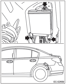
3) Install the canister to the vehicle.
Tightening torque: 8 N*m (0.8 kgf-m, 5.9 ft-lb)
4) Secure the rear wiring harness with clip.
5) Attach all tubes to tube clamp (D), and connect the quick connectors of the vent tube (A), canister drain tube (B) and charge tube (C).
CAUTION:
- Make sure there are no damage or dust on connections. If necessary, clean the seal surface of the pipe.
- Make sure that the quick connector is securely connected.
NOTE: Connect the quick connector as shown in the figure.
- Vent tube (A) and canister drain tube (B)
- Charge tube (C)
6) Install the rear mud guard LH. <Ref. to EI-38, INSTALLATION, Mud Guard.>
7) Lower the vehicle.
8) Install the rear wheel LH.
Tightening torque: 120 N*m (12.2 kgf-m, 88.5 ft-lb)
INSPECTION
1) Check that the canister has no deformation, cracks or other damages.
2) Check that the tube has no cracks, damage or loose part.
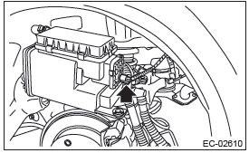
Purge Control Solenoid Valve
A: REMOVAL
1) Disconnect the ground cable from battery.
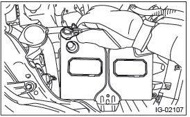
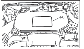
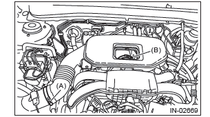
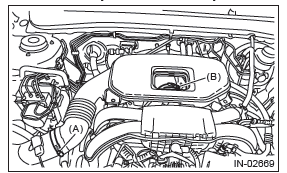
2) Remove the cover (A) and clip (B) from air intake boot assembly.
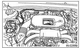
3) Loosen the clamp (A) which connects the air intake boot assembly and air cleaner case.
4) Loosen the clamp (B) which connects the air intake boot assembly and throttle body.
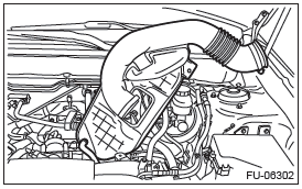
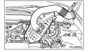
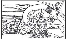
5) Remove the air intake boot from the throttle body, and move it to the left side wheel apron.
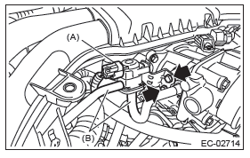
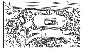
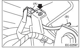
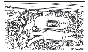
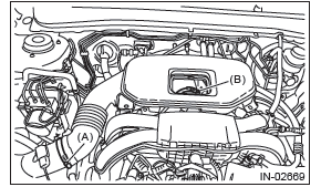
6) Disconnect the purge control solenoid valve connector (A) and evaporation hose (B), and then remove the purge control solenoid valve.
- Other than U5 model
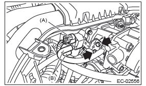
- U5 model
B: INSTALLATION
Install in the reverse order of removal.
NOTE: Connect the evaporation hose as shown in the figure.
- Other than U5 model
- U5 model
- To multifunction duct
- To evaporation line
Tightening torque: 6.4 N*m (0.7 kgf-m, 4.7 ft-lb)
- Other than U5 model
- U5 model

NOTE: Align the clamp hole with the protrusion of the air intake boot assembly.
Tightening torque:
Clamp (A), (B)
3 N*m (0.3 kgf-m, 2.2 ft-lb)
C: INSPECTION
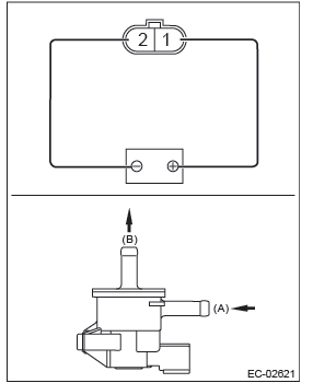
1. PURGE CONTROL SOLENOID VALVE
1) Check that the purge control solenoid valve has no deformation, cracks or other damages.
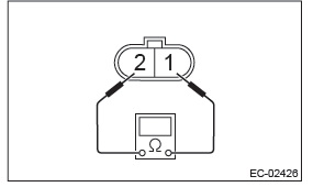
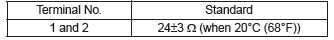
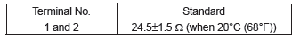
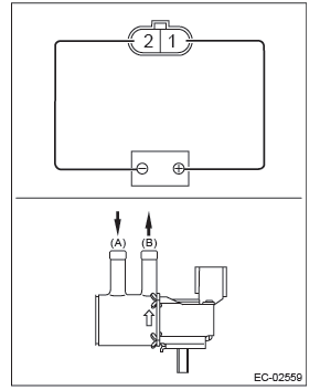
2) Measure the resistance between the purge control solenoid valve terminals.
- Other than U5 model
- U5 model
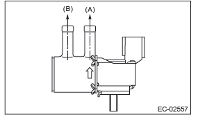
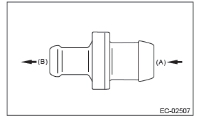
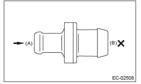
3) Check that air does not come out from (B) when air is blown into (A).
- Other than U5 model
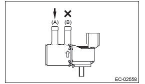
- U5 model
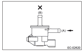
4) Connect the terminal No. 1 to the battery positive terminal and the terminal No. 2 to the battery ground terminal. Check that air is discharged from (B), when supplying air to (A).
- Other than U5 model
- U5 model
2. OTHER INSPECTIONS
Check that the evaporation hose has no cracks, damage or loose part.
EGR Valve
A: REMOVAL
For removal procedures, refer to the "FU(H4SO)" section. <Ref. to FU(H4SO)-36, REMOVAL, EGR Valve.>
B: INSTALLATION
For installation procedure, refer to "FU(H4SO)" section. <Ref. to FU(H4SO)-36, INSTALLATION, EGR Valve.>
C: INSPECTION
For inspection procedures, refer to the "FU(H4SO)" section. <Ref. to FU(H4SO)-36, INSPECTION, EGR Valve.>
Fuel Level Sensor
A: REMOVAL
For removal procedures, refer to the "FU(H4SO)" section. <Ref. to FU(H4SO)-67, REMOVAL, Fuel Level Sensor.>
B: INSTALLATION
For installation procedures, refer to the "FU(H4SO)" section. <Ref. to FU(H4SO)-67, INSTALLATION, Fuel Level Sensor.>
C: INSPECTION
For inspection procedures, refer to the "FU(H4SO)" section. <Ref. to FU(H4SO)-67, INSPECTION, Fuel Level Sensor.>
Fuel Temperature Sensor
A: REMOVAL
The fuel temperature sensor and fuel level sensor are integrated into one unit; therefore, refer to "Fuel Level Sensor" for removal procedure. <Ref. to FU(H4SO)-67, REMOVAL, Fuel Level Sensor.>
- Fuel temperature sensor
B: INSTALLATION
The fuel temperature sensor and fuel level sensor are integrated into one unit; therefore, refer to "Fuel Level Sensor" for installation procedure. <Ref. to FU(H4SO)-67, INSTALLATION, Fuel Level Sensor.>
- Fuel temperature sensor
C: INSPECTION
1) Check that the fuel temperature sensor has no deformation, cracks or other damages.
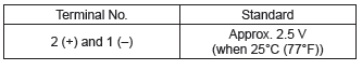
2) Check the resistance between the fuel temperature sensor terminals.
CAUTION: When measuring the resistance, check the circuit tester specification and be careful not to turn on electricity 3 V or more to prevent damaging the fuel temperature sensor.
Fuel Sub Level Sensor
A: REMOVAL
For removal procedures, refer to the "FU(H4SO)" section. <Ref. to FU(H4SO)-69, REMOVAL, Fuel Sub Level Sensor.>
B: INSTALLATION
For installation procedures, refer to the "FU(H4SO)" section. <Ref. to FU(H4SO)-70, INSTALLATION, Fuel Sub Level Sensor.>
C: INSPECTION
For inspection procedures, refer to the "FU(H4SO)" section. <Ref. to FU(H4SO)-70, INSPECTION, Fuel Sub Level Sensor.>
Fuel Tank Pressure Sensor
A: REMOVAL
WARNING: Place "NO OPEN FLAMES" signs near the working area.
1) Disconnect the ground cable from battery.
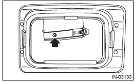
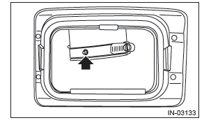
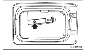
2) Open the fuel filler lid and remove the fuel filler cap.
3) Lift up the vehicle.
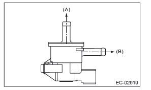
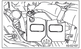
4) Disconnect connector (A) from fuel tank pressure sensor.
5) Pull out the vacuum hose (B) from vehicle.
6) Remove the fuel tank pressure sensor from the bracket.
7) Disconnect the pressure hose from fuel tank pressure sensor and remove the fuel tank pressure sensor.
B: INSTALLATION
Install in the reverse order of removal.
Tightening torque: 7.35 N*m (0.7 kgf-m, 5.4 ft-lb)
C: INSPECTION
1. FUEL TANK PRESSURE SENSOR
1) Check that the fuel tank pressure sensor does not have deformation, cracks or other damages.
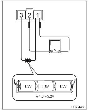
2) Connect dry-cell battery positive terminal to terminal No. 3 and dry-cell battery ground terminal to terminal No. 1, circuit tester positive terminal to terminal No. 2 and the circuit tester negative terminal to terminal No. 1.
NOTE:
- Use new dry-cell batteries.
- Using circuit tester, check the voltage of a single dry-cell battery is 1.6 V or more. And also check the voltage of three batteries in series is between 4.8 V and 5.2 V.
3) Check the voltage at a normal atmospheric pressure.
NOTE: The atmospheric pressure at higher altitude is lower than normal. Therefore, the voltage is lower than the standard value.
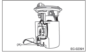
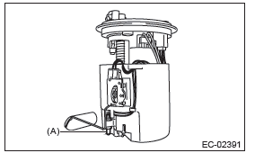
4) Connect the Mighty Vac to the pressure port (A) on the fuel tank pressure sensor.
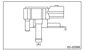
5) Check the voltage when generating vacuum and positive pressure using Mighty Vac.
CAUTION: Be sure to apply pressure within a range of -10 - 20 kPa (-0.1 - 0.2 kgf/cm2, -1.45 - 2.90 psi).
Otherwise the fuel tank pressure sensor will be damaged.
2. OTHER INSPECTIONS
Check that the hose has no cracks, damage or loose part.
Drain Filter
A: SPECIFICATION
Drain valve is a non-disassembled part, so do not remove the drain filter from drain valve. Refer to "Canister" for removal and installation procedures.
<Ref. to EC(H4SO)-5, REMOVAL, Canister.>
<Ref. to EC(H4SO)-6, INSTALLATION, Canister.>
Drain Valve
A: REMOVAL
Drain valve is integrated with canister. Refer to "Canister" for removal procedure. <Ref. to EC(H4SO)-5, REMOVAL, Canister.>
B: INSTALLATION
Refer to "Canister" for the installation procedure.
<Ref. to EC(H4SO)-6, INSTALLATION, Canister.>
C: INSPECTION
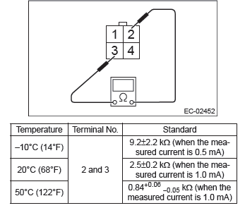
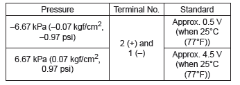
Check the resistance between drain valve terminals.
PCV Hose Assembly
A: REMOVAL
CAUTION: Do not remove except when the PCV hose is broken.
1) Remove the cover (A) and clip (B) from air intake boot assembly.
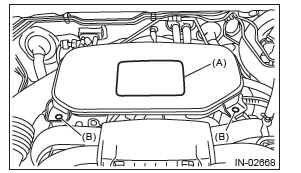
2) Loosen the clamp (A) which connects the air intake boot assembly and air cleaner case.
3) Loosen the clamp (B) which connects the air intake boot assembly and throttle body.
4) Remove the air intake boot from the throttle body, and move it to the left side wheel apron.
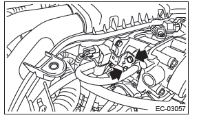
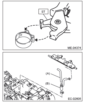
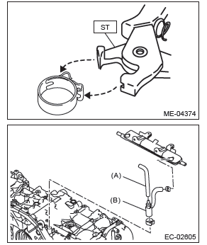
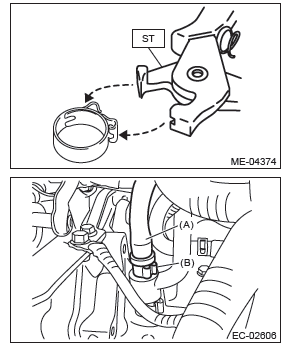
5) Disconnect the vacuum hose (A) from PCV valve, and remove the PCV hose assembly (B) from cylinder block RH and PCV pipe.
NOTE: Pinch the clamp of the PCV hose assembly (B) by fitting the cut out in the ST with the protrusion on the clamp as shown in the figure, and unlock the clamp.
ST 18353AA000 CLAMP PLIERS
B: INSTALLATION
1) Install the PCV hose assembly (B) to the cylinder block RH and PCV pipe, and then connect the vacuum hose (A) to the PCV valve.
NOTE: Use a new clamp for the PCV hose assembly (B), fit the cut out in the ST with the protrusion on the clamp as shown in the figure, and lock the clamp.
ST 18353AA000 CLAMP PLIERS
2) Install the air intake boot assembly.
NOTE: Align the clamp hole with the protrusion of the air intake boot assembly.
Tightening torque:
Clamp (A), (B)
3 N*m (0.3 kgf-m, 2.2 ft-lb)
C: INSPECTION
Check the PCV hose assembly for cracks, damage or looseness.
PCV Valve
A: REMOVAL
CAUTION:
Do not remove unless the PCV valve is broken.
1) Remove the cover (A) and clip (B) from air intake boot assembly.
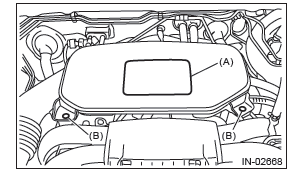
2) Loosen the clamp (A) which connects the air intake boot assembly and air cleaner case.
3) Loosen the clamp (B) which connects the air intake boot assembly and throttle body.
4) Remove the air intake boot from the throttle body, and move it to the left side wheel apron.
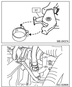
5) Disconnect the vacuum hose (A) and PCV hose (B) from the PCV valve and remove the PCV valve.
NOTE: Pinch the clamp of the PCV hose (B) by fitting the cut out in the ST with the protrusion on the clamp as shown in the figure, and unlock the clamp.
ST 18353AA000 CLAMP PLIERS
B: INSTALLATION
1) Connect the vacuum hose (A) and PCV hose (B) to the PCV valve.
NOTE: Use a new clamp for the PCV hose (B), fit the cut out in the ST with the protrusion on the clamp as shown in the figure, and lock the clamp.
ST 18353AA000 CLAMP PLIERS
2) Install the air intake boot assembly.
NOTE: Align the clamp hole with the protrusion of the air intake boot assembly.
Tightening torque:
Clamp (A), (B)
3 N*m (0.3 kgf-m, 2.2 ft-lb)
C: INSPECTION
1. PCV VALVE
1) Check that the PCV valve has no deformation, cracks or other damages.
2) Check that air is discharged from (B) when air is blown into (A).
3) Check that air does not come out from (B) when air is blown into (A).
2. OTHER INSPECTIONS
Check the vacuum hose for cracks, damage or looseness.
READ NEXT:
 Intake (Induction)
General Description
A: COMPONENT
Air intake duct
Clip
Resonator chamber
Air cleaner case (front)
Spacer
Cushion
Air cleaner element
Air cleaner case (rear)
Clip
Clamp
Cover
Clip
Air int
General Description of Mechanical
A: SPECIFICATION
NOTE:
US: Undersize OS: Oversize
B: COMPONENT
1. V-BELT
V-belt
V-belt cover bracket
V-belt tensioner ASSY
Power steering pump bracket
Generator
SEE MORE:
Basic Diagnostic Procedure of LAN System
A: PROCEDURE
CAUTION:
Subaru Select Monitor is required for reading DTC, performing diagnosis, reading current data, customizing and active test (compulsory drive).
Remove foreign matter (dust, water, oil, etc.) from each control module connector during removal and installation.
To set cruise control
1. Press the “CRUISE” main switch button.
The cruise control indicator light on the combination meter will illuminate.
2. Depress the accelerator pedal until the vehicle reaches the desired speed.
3. Press the “RES/SET” switch to the “SET” side and release it. Then release
the
