Subaru Outback (BR): Intake (Induction)
General Description
A: COMPONENT
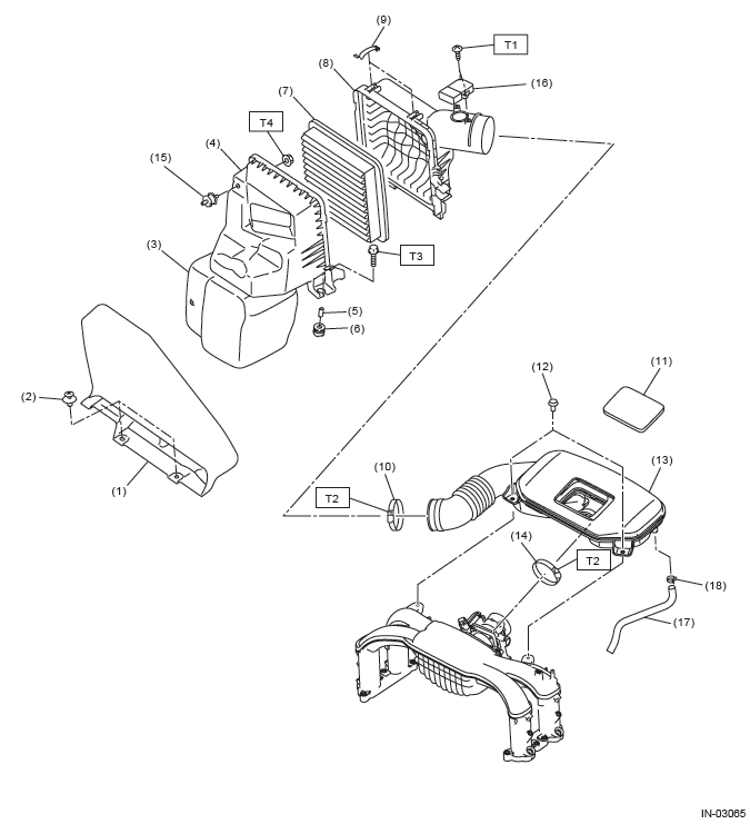
- Air intake duct
- Clip
- Resonator chamber
- Air cleaner case (front)
- Spacer
- Cushion
- Air cleaner element
- Air cleaner case (rear)
- Clip
- Clamp
- Cover
- Clip
- Air intake boot ASSY
- Clamp
- Cushion
- Mass air flow and intake air temperature sensor
- Blow-by hose
- Clip
Tightening torque: N*m (kgf-m, ft-lb)
T1: 1 (0.1, 0.7)
T2: 3 (0.3, 2.2)
T3: 6 (0.6, 4.4)
T4: 7.5 (0.8, 5.5)
B: CAUTION
- Wear appropriate work clothing, including a cap, protective goggles and protective shoes when performing any work.
- Remove contamination including dirt and corrosion before removal, installation or disassembly.
- Keep the disassembled parts in order and protect them from dust and dirt.
- Before removal, installation or disassembly, be sure to clarify the failure. Avoid unnecessary removal, installation, disassembly and replacement.
- Vehicle components are extremely hot after driving.
Be wary of receiving burns from heated parts.
- Be sure to tighten fasteners including bolts and nuts to the specified torque.
- Place shop jacks or rigid racks at the specified points.
- Before disconnecting connectors of sensors or units, be sure to disconnect the ground cable from the battery.
Air Cleaner Element
A: REMOVAL
1) Disconnect the ground cable from battery.
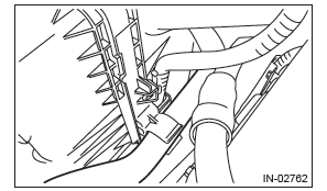
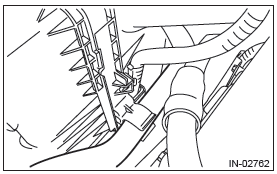
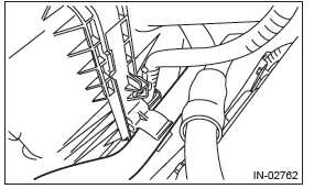
2) Disconnect the power steering oil pressure hose (suction hose) from the clip on the side of air cleaner case (rear).
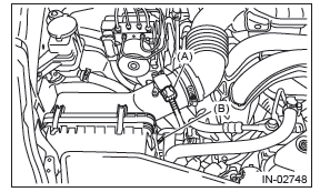
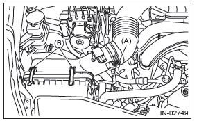
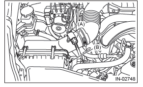
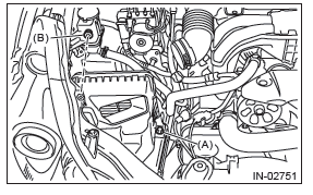
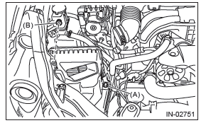
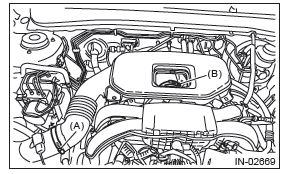
3) Disconnect the connector (A) from the mass air flow and intake air temperature sensor, and remove the clip (B).
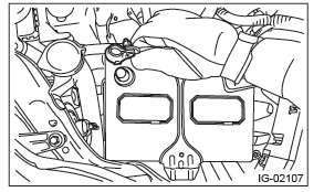
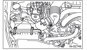
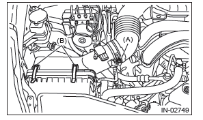
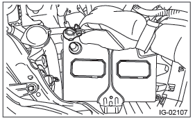
4) Loosen the clamp (A) which connects the air cleaner case (rear) and air intake boot assembly, and then remove the clip (B) from the air cleaner case (front).
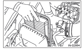
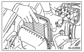
5) Pull the air cleaner case (rear) backward of the vehicle, and remove the air cleaner element.
B: INSTALLATION
Install in the reverse order of removal.
CAUTION: Be sure to use SUBARU genuine air cleaner element depending on the engine type when replacing the air cleaner elements. Using other air cleaner element may affect the engine performance.
NOTE:
- Check that there are no foreign objects in the air cleaner case.
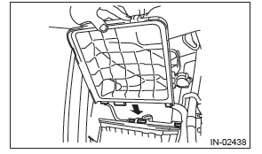
- When installing the air cleaner case (rear), align the protrusion of the air cleaner case (rear) to the hole on the air cleaner case (front) to install.
Tightening torque: 3 N*m (0.3 kgf-m, 2.2 ft-lb)
C: INSPECTION
1) Check that the air cleaner element has no deformation, cracks or other damages.
2) Check the air cleaner element for excessive dirt.
Air Cleaner Case
A: REMOVAL
1) Disconnect the ground cable from battery.
2) Remove the air intake duct. <Ref. to IN(H4SO)- 9, REMOVAL, Air Intake Duct.>
3) Disconnect the power steering oil pressure hose (suction hose) from the clip on the side of air cleaner case (rear).
4) Disconnect the connector (A) from the mass air flow and intake air temperature sensor, and remove the clip (B).
5) Loosen the clamp (A) which connects the air cleaner case (rear) and air intake boot assembly, and then remove the clip (B) from the air cleaner case (front).
6) Remove the air cleaner case (rear) and air cleaner element.
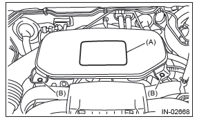
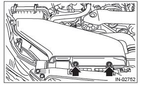
7) Remove bolts (A) and nuts (B) which secure the air cleaner case (front) to the body, and remove the air cleaner case (front).
B: INSTALLATION
1) Install the bolt (A) and nut (B) which secure the air cleaner case (front) to the body.
Tightening torque:
Bolt (A)
6 N*m (0.6 kgf-m, 4.4 ft-lb)
Nut (B)
7.5 N*m (0.8 kgf-m, 5.5 ft-lb)
2) Install the air cleaner case (rear) and air cleaner element.
NOTE: When installing the air cleaner case (rear), align the protrusion of the air cleaner case (rear) to the hole on the air cleaner case (front) to install.

3) Attach the clip (B) to the air cleaner case (front), and tighten the clamp (A) connecting the air cleaner case (rear) and air intake boot assembly.
Tightening torque:
Clamp (A)
3 N*m (0.3 kgf-m, 2.2 ft-lb)
4) Connect the connector (A) to the mass air flow and intake air temperature sensor and secure the harness with clip (B).
5) Connect the power steering oil pressure hose (suction hose) to the clip on the side of air cleaner case (rear).
6) Install the air intake duct. <Ref. to IN(H4SO)-9, INSTALLATION, Air Intake Duct.>
7) Connect the battery ground terminal.
C: INSPECTION
1) Check that the air cleaner case has no deformation, cracks or other damages.
2) Check that the air intake boot has no cracks, damage or loose part.
Air Intake Boot
A: REMOVAL
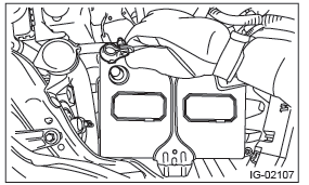
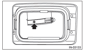
1) Remove the cover (A) and clip (B) from air intake boot assembly.
2) Loosen the clamp (A) which connects the air intake boot assembly and air cleaner case.
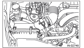
3) Loosen the clamp (B) which connects the air intake boot assembly and throttle body.
4) Disconnect the blow-by hose and remove the air intake boot assembly.
B: INSTALLATION
Install in the reverse order of removal.
NOTE: Align the clamp hole with the protrusion of the air intake boot assembly.
Tightening torque: 3 N*m (0.3 kgf-m, 2.2 ft-lb)
C: INSPECTION
1) Check that the air intake boot assembly does not have deformation, cracks or other damages.
2) Check there is no foreign matter in the air intake boot assembly.
Air Intake Duct
A: REMOVAL
1) Remove the clip which secures the air intake duct, and remove the air intake duct.
B: INSTALLATION
Install in the reverse order of removal.
C: INSPECTION
1) Check that the air intake duct has no deformation, cracks or other damages.
2) Inspect that no foreign objects are mixed in the air intake duct.
Resonator Chamber
A: REMOVAL
The resonator chamber and air cleaner case are integrated into one unit; therefore, refer to "Air Cleaner Case" for removal procedure. <Ref. to IN(H4SO)-6, REMOVAL, Air Cleaner Case.>
B: INSTALLATION
The resonator chamber and air cleaner case are integrated into one unit; therefore, refer to "Air Cleaner Case" for installation procedure. <Ref. to IN(H4SO)-7, INSTALLATION, Air Cleaner Case.>
C: INSPECTION
Check that the resonator chamber has no deformation, cracks or other damages.
READ NEXT:
 General Description of Mechanical
A: SPECIFICATION
NOTE:
US: Undersize OS: Oversize
B: COMPONENT
1. V-BELT
V-belt
V-belt cover bracket
V-belt tensioner ASSY
Power steering pump bracket
Generator
Engine Assembly
A: REMOVAL
1) Change the front hood damper mounting position
from (A) to (B), and completely open the front
hood.
Tightening torque:
20 N*m (2.0 kgf-m, 14.8 ft-lb)
2) Remove the V-belt covers.
3) C
SEE MORE:
Fuses
CAUTION
Never replace a fuse with one having a higher rating or with material other than
a fuse because serious damage or a fire could result.
The fuses are designed to melt during an overload to prevent damage to the wiring
harness and electrical equipment. The fuses are located in two fuse b
Front Inner Remote
A: REMOVAL
1) Remove the door trim. <Ref. to EI-60, REMOVAL, Door Trim.>
2) Remove the screws to detach the front inner remote handle.
B: INSTALLATION
1) Before installation, check the following items.
Cable is free from deformation such as fray.
Grease is applied sufficiently to cable jo
