Subaru Outback (BR): AT Shift Lock Control System
Subaru Outback (BR) 2010-2015 Service Manual / Transmission / Control Systems / AT Shift Lock Control System
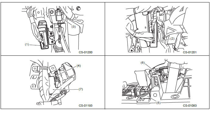
A: LOCATION
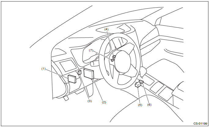
- TCM ("P" range)
- Body integrated unit
- Stop light switch
- Key cylinder (with built-in key warning switch)
- Solenoid unit
- "P" range switch
- Key lock solenoid
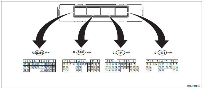
B: ELECTRICAL SPECIFICATION
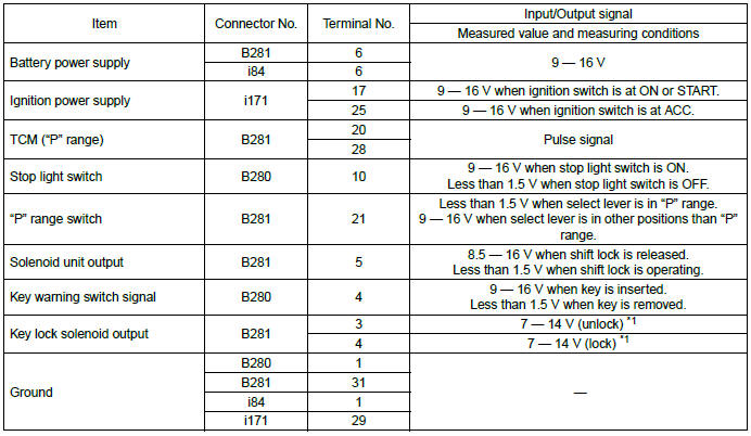
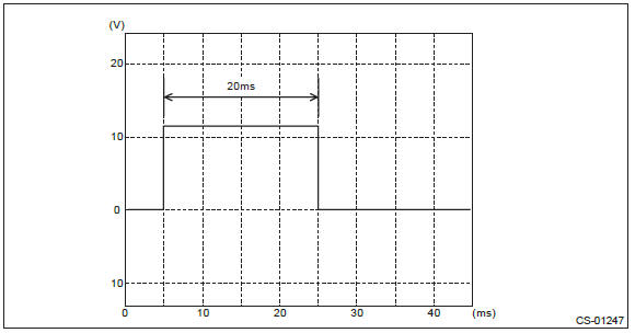
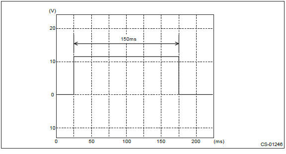
*1: Measuring condition
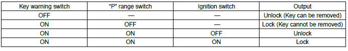
Output signal for key lock solenoid (unlock)
Output signal for key lock solenoid (lock)
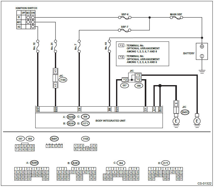
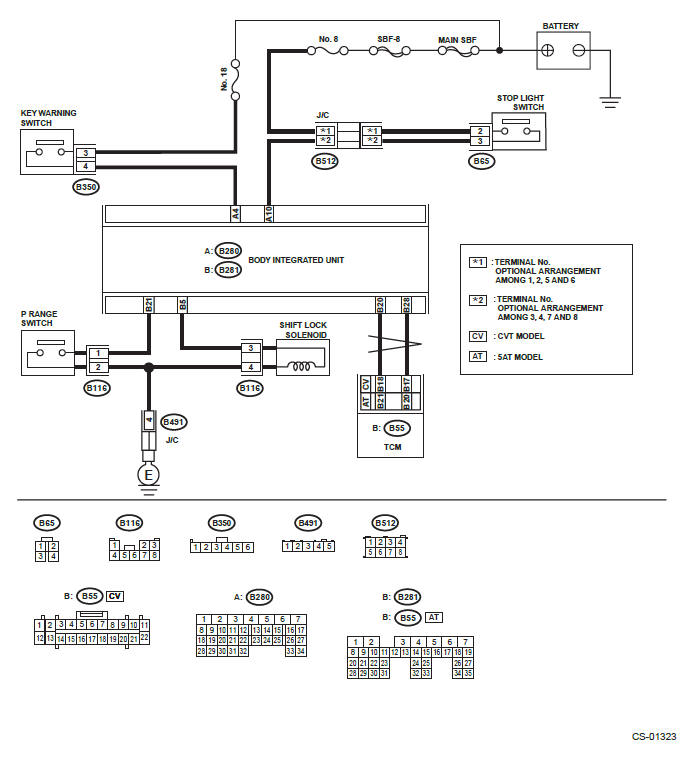
C: WIRING DIAGRAM
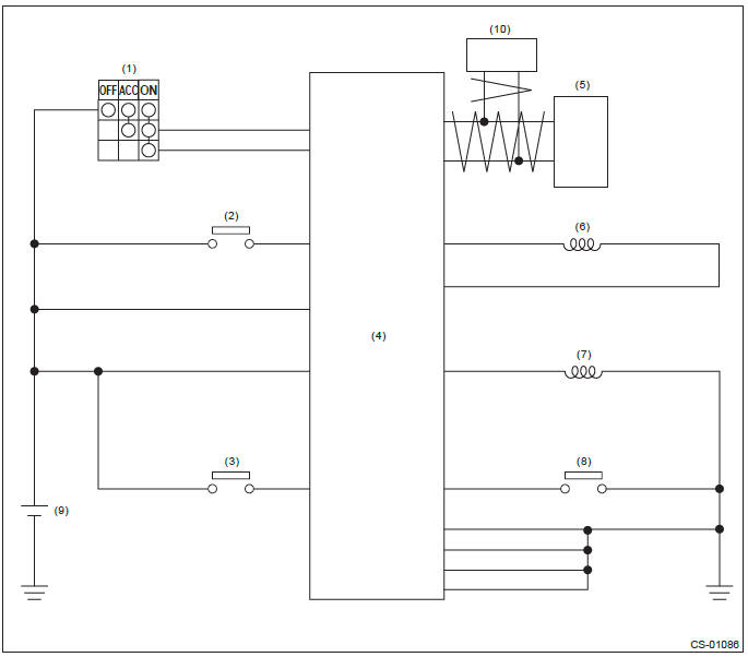
- Ignition switch
- Stop light switch
- Key warning switch
- Body integrated unit
- TCM (shift range information)
- Key lock solenoid
- Solenoid unit
- "P" range switch
- Battery
- VDC (vehicle speed information)
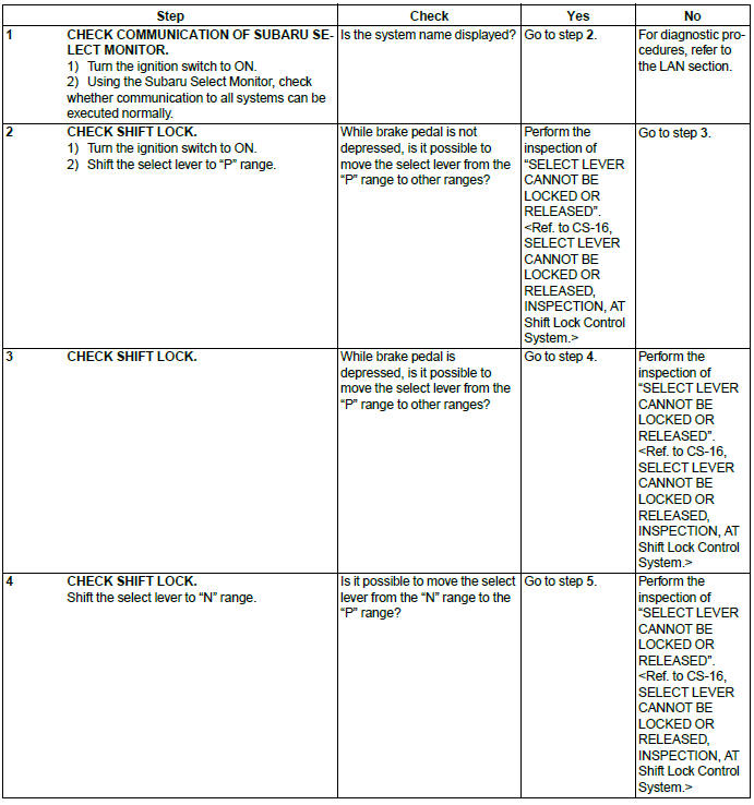
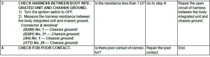
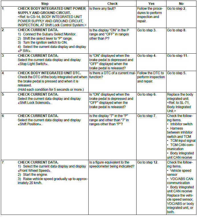
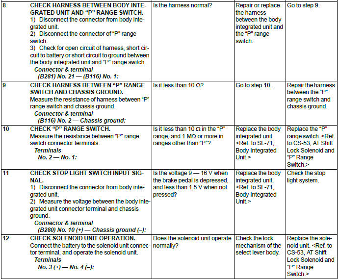
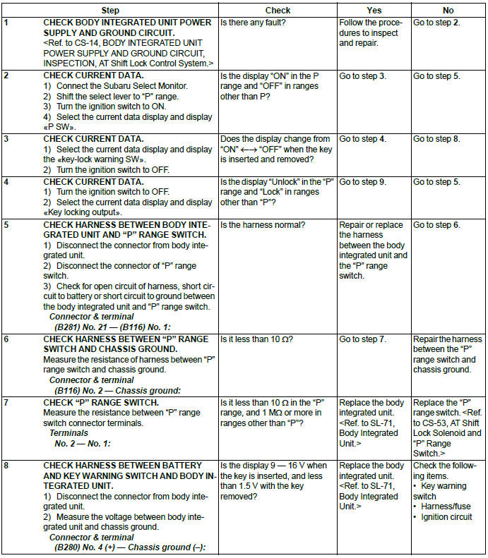
D: INSPECTION
1. SHIFT LOCK OPERATION
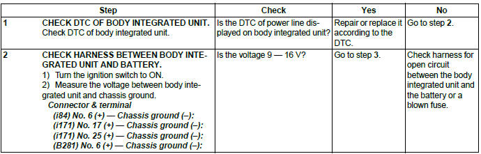
2. BODY INTEGRATED UNIT POWER SUPPLY AND GROUND CIRCUIT
NOTE: For the DC power supply circuit, refer to "WIRING DIAGRAMS". <Ref. to WI-15, Power Supply Circuit.>
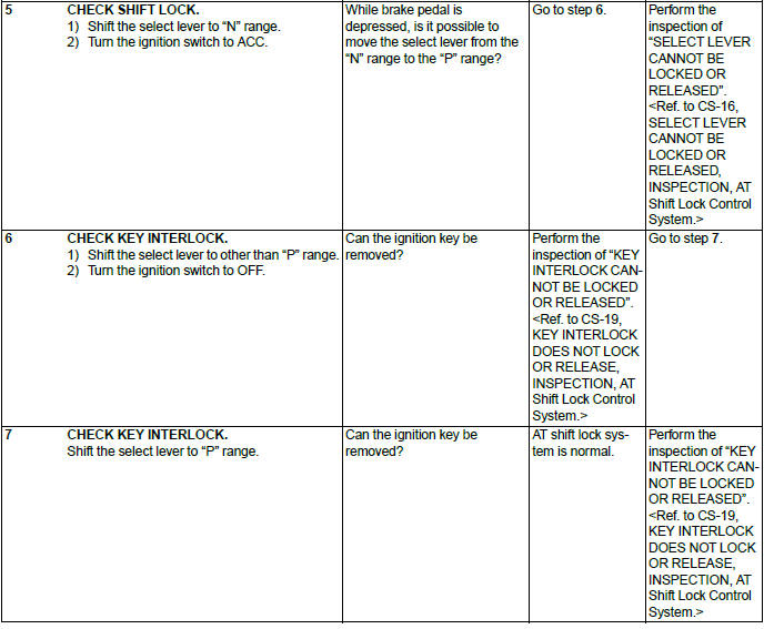
3. SELECT LEVER CANNOT BE LOCKED OR RELEASED
4. KEY INTERLOCK DOES NOT LOCK OR RELEASE
READ NEXT:
 Select Lever (removal, installation, disassembly, inspection)
A: REMOVAL
1) Shift the select lever to "N" range.
2) Disconnect the ground cable from battery.
3) Lift up the vehicle.
4) Remove the rear exhaust pipe.
2.5 L non-turbo model <
Select Cable
A: REMOVAL
1) Shift the select lever to "N" range.
2) Disconnect the ground cable from battery.
3) Lift up the vehicle.
4) Remove the front exhaust pipe and rear exhaust pipe.
2.5 L model
<Re
MT Gear Shift Lever
A: REMOVAL
1) Disconnect the ground cable from battery.
2) Lift up the vehicle.
3) Remove the center exhaust pipe and rear exhaust pipe. (non-turbo model) <Ref.
to EX(H4SO)-8, REMOVAL,
Center Ex
SEE MORE:
Installation of child restraint systems by use of lower and tether anchorages
(LATCH)
WARNING
● Child restraint systems and seatbelts can become hot in a vehicle that has
been closed up in sunny weather; they could burn a small child. Check the child
restraint system before you place a child in it.
● Do not leave an unsecured child restraint system in your vehicle.
Outback License plate light
1. Remove the mounting screws using a Phillips screwdriver.
2. Remove the lens.
3. Pull the bulb out of the socket.
4. Install a new bulb.
5. Reinstall the lens.
6. Tighten the mounting screws.
© 2010-2026 Copyright www.suoutback.com
