Subaru Outback (BR): Clutch Pedal
A: REMOVAL
1) Disconnect the ground cable from battery.
2) Remove the collector cover. (turbo model)
3) Remove the air intake boot assembly. (non-turbo model) <Ref. to IN(H4SO)-8, INSTALLATION, Air Intake Boot.>
4) Remove the intercooler. (turbo model) <Ref. to IN(H4DOTC)-17, REMOVAL, Intercooler.>
5) Drain the clutch fluid from the reservoir tank.
6) Disconnect the clutch pipe from the connector.
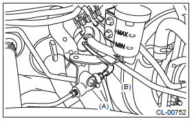
- Connector
- Clutch pipe
7) Disconnect the reservoir tank hose from the reservoir tank.
- Reservoir tank
- Reservoir tank hose
- Clamp
8) Remove the instrument panel lower cover. <Ref. to EI-64, REMOVAL, Instrument Panel Lower Cover.>
9) Remove the body integrated unit. <Ref. to SL- 71, REMOVAL, Body Integrated Unit.>
10) Disconnect the connector from clutch switch.
11) Disconnect the connector from the brake switch.
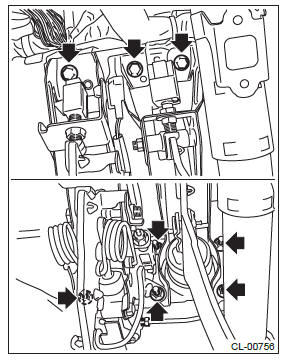
12) Remove the snap pin and clevis pin connecting the operating rod and brake pedal.
13) Remove the pedal assembly.
NOTE: Place vinyl, etc. in order not to drop the clutch fluid to the floor carpet.
B: INSTALLATION
1) Install in the reverse order of removal.
CAUTION: Always use a new clevis pin.
Tightening torque: T: 18 N*m (1.8 kgf-m, 13.3 ft-lb)
2) Fill the recommended clutch fluid. <Ref. to CL- 24, Clutch Fluid.>
3) Bleed air from the clutch system. <Ref. to CL-25, PROCEDURE, Clutch Fluid Air Bleeding.>
4) Adjust the clutch pedal. <Ref. to CL-29, ADJUSTMENT, Clutch Pedal.>
5) When the clutch pedal has been replaced, perform the clutch sensor calibration mode. <Ref. to PB(diag)-20, CLUTCH SENSOR CALIBRATION MODE, OPERATION, Subaru Select Monitor.>
NOTE: If necessary, perform the clutch meet position setting.
<Ref. to PB(diag)-20, CLUTCH ENGAGEMENT POSITION SETTING, OPERATION, Subaru Select Monitor.>
6) Install the collector cover.
C: DISASSEMBLY
1) Disconnect the clutch pipe from the master cylinder.
2) Remove the clutch damper mounting nut from the pedal assembly, and disconnect the clutch pipe from the clamp.
3) Remove the clutch switches.
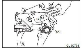
4) Remove the clip and pull out the clevis pin.
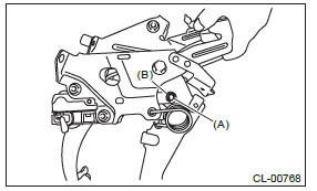
- Clevis pin
- Clip
5) Disconnect the connector from the clutch stroke sensor, and then remove the sensor harness.
6) Remove the master cylinder from the pedal assembly.
NOTE: Secure the push rod with a tape, etc. to prevent it from falling off.
- Master cylinder
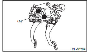
7) Remove the torsion spring and assist bushing from the pedal assembly.
- Torsion spring
- Assist bushing
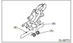
8) Remove the clutch pedal from the pedal bracket.
NOTE: Before removing the clutch pedal mounting bolt, remove the hook of the assist spring from the pedal bracket. (turbo model)
- Clutch pedal
- Assist spring (turbo model)
9) Remove the assist spring (turbo model), bushing, spacer, bushing A, stopper, torsion spring bushing and clutch pedal pad from the clutch pedal.
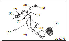
- Assist spring (turbo model)
- Bushing
- Spacer
- Bushing A
- Stopper
- Torsion spring bushing
- Clutch pedal pad
- Clutch pedal
D: ASSEMBLY
1) Clean the holes in the sliding surface between the clutch pedal and pedal bushing, and apply grease.
2) Attach the pedal pad, stopper, assist spring (turbo model), bushing A, torsion spring bushing, spacer and bushing to the clutch pedal.
NOTE: Before installing the spacer, clean the inside of the pedal bushings and apply grease.
3) Attach the clutch pedal to the pedal bracket.
NOTE:
- Before installing the assist spring, apply grease to the coil part of the assist spring. (turbo model)
- Hang hook of the assist spring on the pedal bracket. (turbo model)
Tightening torque: T: 30 N*m (3.1 kgf-m, 22.1 ft-lb)
- Clutch pedal
- Assist spring (turbo model)
4) Install the assist bushing and torsion spring to the pedal assembly.
NOTE: Before installing the torsion spring, apply grease to the assist bushing and torsion spring bushing.
5) Install the master cylinder to the pedal assembly.
NOTE: Secure the push rod with a tape, etc. to prevent it from falling off.
Tightening torque: T: 18 N*m (1.8 kgf-m, 13.3 ft-lb)
- Master cylinder
6) Secure the clevis pin with mounting clip.
CAUTION: Always use a new clevis pin.
NOTE: Before installing the clevis pin, apply grease.
- Clevis pin
- Clip
7) Attach the sensor harness, and connect the connector to the clutch stroke sensor.
8) Install the clutch switch.
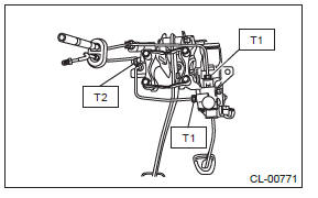
9) Install the clutch damper to the pedal assembly, and connect the clutch pipe to the master cylinder.
Tightening torque:
T1: 15 N*m (1.5 kgf-m, 11.1 ft-lb)
T2: 18 N*m (1.8 kgf-m, 13.3 ft-lb)
E: INSPECTION
1. CLUTCH PEDAL
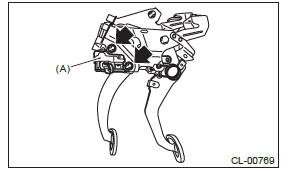
Move the clutch pedal in the lateral direction with a force of approximately 10 N (1 kgf, 2 lbf) to check that the clutch pedal deflection is within the service limit.
CAUTION: If the deflection exceeds the service limit, replace with a new clutch pedal assembly.
Deflection of the clutch pedal: Service limit 4.0 mm (0.157 in) or less
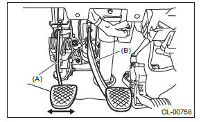
- Clutch pedal
- Brake pedal
F: ADJUSTMENT
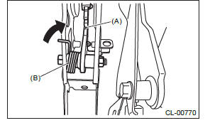
1) If the full stroke of the clutch pedal is not within the specified value, loosen the lock nuts of the clutch switch and adjust the full stroke of the clutch pedal with the clutch switch.
CAUTION: When adjusting the full stroke of clutch pedal, do not turn the clutch switch.
Clutch pedal full stroke A:
130 - 135 mm (5.12 - 5.31 in) (non-turbo
model)
135 - 140 mm (5.31 - 5.51 in) (turbo model)
Tightening torque: T: 8 N*m (0.8 kgf-m, 5.9 ft-lb)

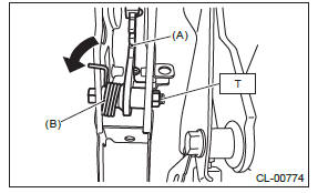
2) Depress and release the clutch pedal two or three times to ensure that the clutch pedal and release lever operate smoothly. If the clutch pedal and release lever do not operate smoothly, bleed air from the clutch hydraulic system. <Ref. to CL- 25, Clutch Fluid Air Bleeding.>
3) Measure the clutch pedal full stroke length again to ensure that it is within specifications. If it is not within specifications, repeat adjustment procedures again from the beginning.
Clutch pedal full stroke:
130 - 135 mm (5.12 - 5.31 in) (non-turbo
model)
135 - 140 mm (5.31 - 5.51 in) (turbo model)
4) Push the release lever until the operating cylinder push rod retracts. Make sure that the clutch fluid level in the reservoir tank increases. If the clutch fluid level increases, the hydraulic clutch is properly adjusted; If the clutch fluid level does not increase or the push rod does not retract, replace the master cylinder with a new part. <Ref. to CL-20, Master Cylinder.>
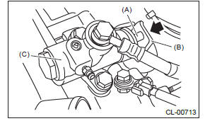
- Push rod
- Release lever
- Operating cylinder
5) Push the release lever until the operating cylinder push rod retracts. Check that the clutch fluid level in the reservoir tank increases.
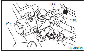
- Push rod
- Release lever
- Operating cylinder
6) If the clutch fluid level increases, hydraulic clutch play is correct.
7) If the clutch fluid level does not increase or push rod does not retract, readjust the clutch pedal.
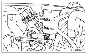
8) Check the clutch fluid level using the scale on the outside of the reservoir tank. If the clutch fluid level is below "MIN", fill the clutch fluid up to "MAX" level.
Recommended clutch fluid: New FMVSS No. 116 DOT3
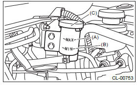
- MAX. level
- MIN. level
- Reservoir tank
READ NEXT:
 Clutch Switch
A: REMOVAL
1) Disconnect the ground cable from battery.
2) Remove the instrument panel lower cover. <Ref.
to EI-64, REMOVAL, Instrument Panel Lower Cover.>
3) Disconnect the connector from clu
SEE MORE:
Differential Gear Oil replacement
A: INSPECTION
1) Remove the filler plug, and then check the gear oil. Replace the gear oil if it is contaminated, deteriorated or cloudy. <Ref. to DI-23, REPLACEMENT, Differential Gear Oil.>
2) Check that the gear oil level is within -5 mm (- 0.2 in) from the bottom of the filler plug hole.
General Description of Seat Belt System
A: COMPONENT
1. FRONT SEAT BELT
Adjustable anchor ASSY
Outer belt ASSY
Seat belt retractor ASSY (Outer belt ASSY)
Center pillar trim UPR
Inner belt ASSY
Tightening torque: N*m (kgf-m, ft-lb)
T1: 7.5 (0.76, 5.5)
T2: 30 (3.06, 22.1)
T3: 38 (3.87, 28.0)
T4: 53 (5.4
