Subaru Outback (BR): Clutch Switch
A: REMOVAL
1) Disconnect the ground cable from battery.
2) Remove the instrument panel lower cover. <Ref. to EI-64, REMOVAL, Instrument Panel Lower Cover.>
3) Disconnect the connector from clutch switch.
4) Remove the clutch switches.
B: INSTALLATION
1. CLUTCH SWITCH
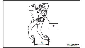
1) Move the clevis pin of push rod to left and right, retain it at the position where it moves smoothly, and measure the clutch pedal stroke.
Clutch pedal full stroke A:
130 - 135 mm (5.12 - 5.31 in) (non-turbo
model)
135 - 140 mm (5.31 - 5.51 in) (turbo model)
Tightening torque: T: 8 N*m (0.8 kgf-m, 5.9 ft-lb)
2) If the clutch pedal stroke is out of specification, adjust the stroke. <Ref. to CL-29, ADJUSTMENT, Clutch Pedal.>
3) Connect the connector to the clutch switch.
2. CLUTCH START SWITCH
1) Fully depress the clutch pedal and hold it.
2) Install so that gap (A) of the clutch pedal plate and clutch start switch is 2.9 mm (0.11 in), and tighten the lock nut.
Tightening torque: 8 N*m (0.8 kgf-m, 5.9 ft-lb)
- 2.9 mm (0.11 in)
- Clutch pedal plate
- Clutch start switch
- Lock nut
3) Connect the connector to the clutch start switch.
4) Make sure that engine does not start with clutch pedal not depressed.
5) Make sure that engine starts with clutch pedal fully depressed.
C: INSPECTION
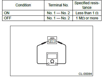
1. CLUTCH START SWITCH
1) Perform the following inspections. If the clutch start switch does not operate normally, adjust the switch, and check it again. <Ref. to CL-33, ADJUSTMENT, Clutch Switch.>
- Make sure that engine does not start with clutch pedal not depressed.
- Make sure that engine starts with clutch pedal fully depressed.
2) When the clutch start switch does not operate normally even if it is adjusted, check the clutch start switch for continuity.
- Remove the clutch start switch. <Ref. to CL- 31, REMOVAL, Clutch Switch.>
- Measure the resistance between terminal 1 and 2 of the switch. If the resistance is not at the standard value, replace the switch.
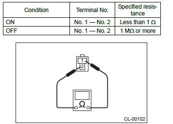
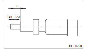
- Check that the switch is turned on and off in Dimension L.
Dimension L: 4 - 5.5 mm (0.16 - 0.22 in)
- ON
- OFF
2. CLUTCH SWITCH
1) Check the clutch switch for continuity.
- Disconnect the connector of clutch switch.
- Measure the resistance between terminal 1 and 2 of the switch. If the resistance is not within the specification, check the clutch stroke and installation condition, and check the clutch switch again.
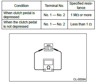
2) When the clutch switch does not operate normally even if the clutch stroke and installation condition are normal, check the clutch switch for continuity.
- Remove the clutch switches. <Ref. to CL- 31, REMOVAL, Clutch Switch.>
- Measure the resistance between terminal 1 and 2 of the switch. If the resistance is not at the standard value, replace the switch.
- Check that the switch is turned on and off in Dimension L.
Dimension L: 5 - 6.5 mm (0.2 - 0.26 in)
- ON
- OFF
D: ADJUSTMENT
1) Loosen the lock nut of the clutch start switch.
2) Fully depress the clutch pedal and hold it.
3) Adjust the gap (A) of the clutch pedal plate and the clutch start switch to be 2.9 mm (0.11 in).
- 2.9 mm (0.11 in)
- Clutch pedal plate
- Clutch start switch
- Lock nut
4) Tighten the lock nut.
Tightening torque: 8 N*m (0.8 kgf-m, 5.9 ft-lb)
General Diagnostic Table
A: INSPECTION
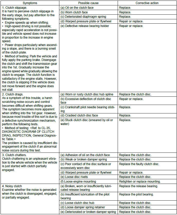
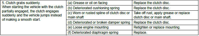
1. CLUTCH
2. CLUTCH PEDAL

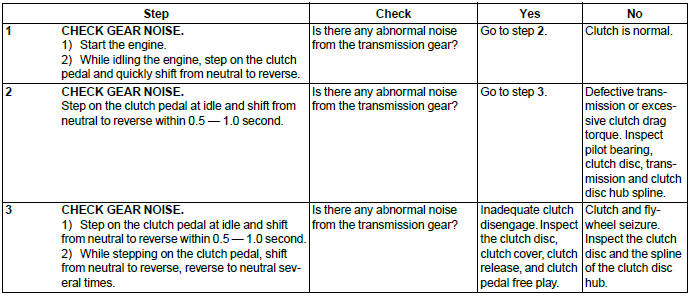
3. DIAGNOSTIC DIAGRAM OF CLUTCH DRAG
READ NEXT:
 General Description of Front Suspension
A: SPECIFICATION
*1: OUTBACK model
2+-3 mm (0.08 - 0.12 in) Toe angle (sum of both wheels): 0º10′+-0º15′
*2: Except for OUTBACK model
0+-3 mm (0+-0.12 in) Toe angle (sum of
SEE MORE:
Cylinder Block
A: REMOVAL
NOTE:
Before conducting this procedure, drain the engine
oil completely.
1) Remove the engine from the vehicle. <Ref. to
ME(H4SO)-31, REMOVAL, Engine Assembly.>
2) Remove the intake manifold. <Ref. to
FU(H4SO)-17, REMOVAL, Intake Manifold.>
3) Remove the crank pulley. <R
Tire rotation
Vehicles equipped with 4 non-unidirectional tires
1) Front
Vehicles equipped with unidirectional tires
1) Front
Tire wear varies from wheel to wheel. To maximize the life of each tire and ensure
that the tires wear uniformly, it is best to rotate the tires every 7,500 miles
(12,000 km).
