Subaru Outback (BR): Crankshaft Position Sensor
A: REMOVAL
1) Disconnect the ground cable from battery.
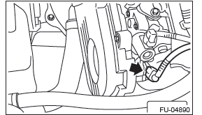
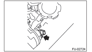
2) Remove the bolt which secures crankshaft position sensor to oil pump.
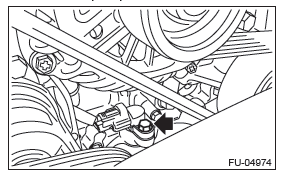
3) Remove the crankshaft position sensor, and disconnect the connector from the crankshaft position sensor.
B: INSTALLATION
Install in the reverse order of removal.
Tightening torque: 6.4 N*m (0.7 kgf-m, 4.7 ft-lb)
C: INSPECTION
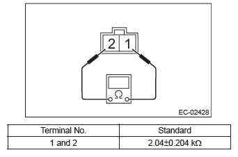
1. CRANKSHAFT POSITION SENSOR (METHOD WITH CIRCUIT TESTER)
Measure the resistance between crankshaft position sensor terminals.
2. CRANKSHAFT POSITION SENSOR (METHOD WITH OSCILLOSCOPE)
1) Prepare an oscilloscope.
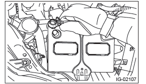
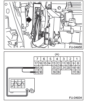
2) Remove the glove box lid assembly.
3) Connect the probe to ECM connector.
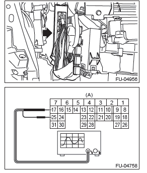
- To ECM connector

4) Start the engine and let it idle.
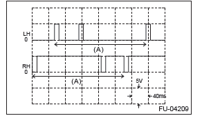
5) Check the pattern is the same as the waveform and voltage shown below.
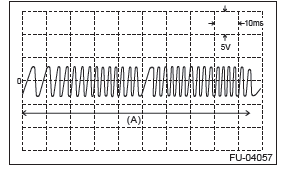
- One crankshaft rotation
6) After inspection, install the related parts in the reverse order of removal.
3. OTHER INSPECTIONS
Check that the crankshaft position sensor has no deformation, cracks or other damages.
Camshaft Position Sensor
A: REMOVAL
1) Disconnect the ground cable from battery.
2) Disconnect the connector from camshaft position sensor.
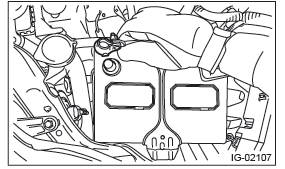
3) Remove the ignition coil. (LH side only)
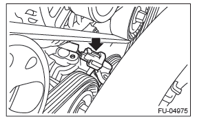
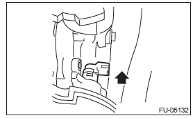
4) Remove the bolt which secures camshaft position sensor to camshaft position sensor support.
5) Remove the bolt which secures camshaft position sensor support to camshaft cap LH.
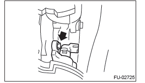
6) Remove the camshaft position sensor and the camshaft position sensor support as a unit.
NOTE: Slide in the arrowed direction until the camshaft position sensor contacts the rocker cover LH.
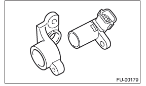
7) Remove the camshaft position sensor from the camshaft position sensor support.
B: INSTALLATION
Install in the reverse order of removal.
Tightening torque:
Camshaft position sensor support
6.4 N*m (0.7 kgf-m, 4.7 ft-lb)
Camshaft position sensor
6.4 N*m (0.7 kgf-m, 4.7 ft-lb)
C: INSPECTION
1. CAMSHAFT POSITION SENSOR (METHOD WITH OSCILLOSCOPE)
1) Prepare an oscilloscope.
2) Remove the glove box lid assembly.
3) Connect the probe to ECM connector.
- To ECM connector

4) Start the engine and let it idle.
5) Check the pattern is the same as the waveform and voltage shown below.
- One camshaft rotation
6) After inspection, install the related parts in the reverse order of removal.
2. OTHER INSPECTIONS
Check that the camshaft position sensor has no deformation, cracks or other damages.
READ NEXT:
 Knock Sensor
A: REMOVAL
1) Disconnect the ground cable from battery.
2) Remove the cover (A) and clip (B) from air intake
boot assembly.
3) Loosen the clamp (A) which connects the air intake
boot assembly and ai
Manifold Absolute Pressure
Sensor
A: REMOVAL
1) Disconnect the ground cable from battery.
2) Remove the cover (A) and clip (B) from air intake
boot assembly.
3) Loosen the clamp (A) which connects the air intake
boot assembly and ai
Oil Temperature Sensor
A: REMOVAL
1) Disconnect the ground cable from battery.
2) Remove the cover (A) and clip (B) from air intake
boot assembly.
3) Loosen the clamp (A) which connects the air intake
boot assembly and ai
SEE MORE:
Automatic Transmission Control Device
A: REMOVAL
1) Remove the transmission assembly from the vehicle.
<Ref. to 5AT-37, REMOVAL, Automatic Transmission Assembly.>
2) Pull out the torque converter assembly. <Ref. to 5AT-63, REMOVAL, Torque Converter Assembly.>
3) Lift up the lever on the rear side of transmission harness
Electronic parking brake
1) Parking brake switch
2) Hill Holder switch
3) Indicator light
WARNING
● Before exiting the vehicle, make sure that you turn off the engine. Otherwise,
the parking brake may be released and an accident may occur.
● If the brake system warning light flashes, the electronic park
