Subaru Outback (BR): DTC P0026, P0028, P0030, P0031, P0032, P0037, P0038, P0068, P0076, P0077, P0082, P0083, P0101, P0102, P0103
A: DTC P0026 INTAKE VALVE CONTROL SOLENOID CIRCUIT RANGE/PERFORMANCE (BANK 1)
1. OUTLINE OF DIAGNOSIS
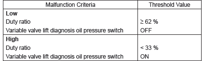
Judge as NG with either Low NG or High NG.
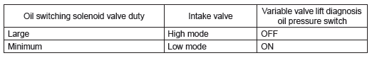
A variable valve lift diagnosis oil pressure switch is installed for diagnosis. It is possible to determine whether the intake valve is in high mode (increase the amount of lift) or in low mode (suppressing the amount of lift) when the variable valve lift diagnosis oil pressure switch is turned ON or OFF.
- Normal
- Low NG
When the variable valve lift diagnosis oil pressure switch remains ON even though the intake valve tried to enter high mode (oil switching solenoid valve duty is large), this is judged as a Low NG.
- High NG
When the variable valve lift diagnosis oil pressure switch remains OFF even though the intake valve tried to enter low mode (oil switching solenoid valve duty is small), this is judged as a High NG.
2. COMPONENT DESCRIPTION
The variable valve lift system optimizes the intake valve lift by switching between the low lift cam and the high lift cam according to the engine speed. The amount of intake valve lift is varied by controlling the oil switching solenoid valve duty according to signals from the ECM.
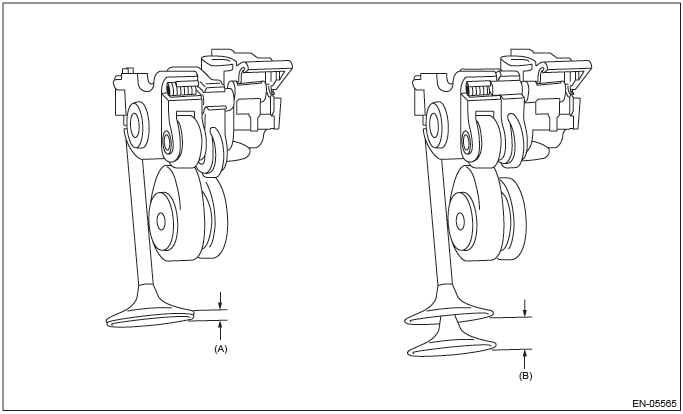
- Low lift
- High lift
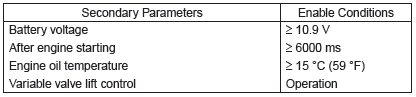
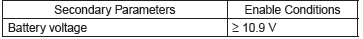
3. ENABLE CONDITION
4. GENERAL DRIVING CYCLE
Perform the diagnosis continuously 6 seconds after engine start while variable valve lift is being controlled.
5. DIAGNOSTIC METHOD
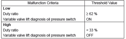
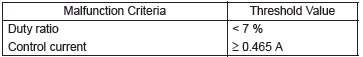
- Abnormality Judgment
If the duration of time while the following conditions are met is longer than the time indicated, judge as NG.
Judgment Value
Time Needed for Diagnosis:
Low side: 784 ms
High side: 3000 ms
Malfunction Indicator Light Illumination: Illuminates as soon as a malfunction occurs.
- Normality Judgment
Judge as OK and clear the NG if the continuous time while the following conditions are established is more than the predetermined time.
Judgment Value
Time Needed for Diagnosis:
Low side: 208 ms
High side: 3000 ms
B: DTC P0028 INTAKE VALVE CONTROL SOLENOID CIRCUIT RANGE/PERFORMANCE (BANK 2)
1. OUTLINE OF DIAGNOSIS
NOTE: For the detection standard, refer to DTC P0026. <Ref. to GD(H4SO)-9, DTC P0026 INTAKE VALVE CONTROL SOLENOID CIRCUIT RANGE/PERFORMANCE (BANK 1), Diagnostic Trouble Code (DTC) Detecting Criteria.>
C: DTC P0030 HO2S HEATER CONTROL CIRCUIT (BANK 1 SENSOR 1)
1. OUTLINE OF DIAGNOSIS
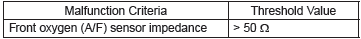
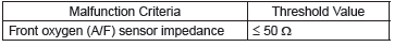
Detect functional errors of the front oxygen (A/F) sensor heater.
Judge as NG when it is determined that the front oxygen (A/F) sensor impedance is large when looking at engine status such as deceleration fuel cut.
2. COMPONENT DESCRIPTION
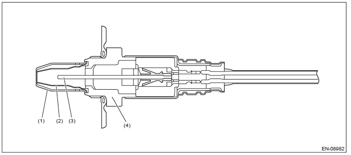
- Element cover (outer)
- Element cover (inner)
- Sensor element
- Sensor housing
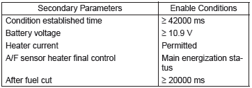
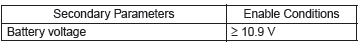
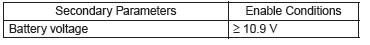
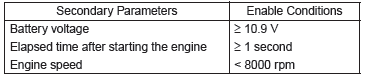
3. ENABLE CONDITION
4. GENERAL DRIVING CYCLE
Perform the diagnosis continuously after 42000 ms or more have passed since the engine started.
5. DIAGNOSTIC METHOD
- Abnormality Judgment
If the duration of time while the following conditions are met is longer than the time indicated, judge as NG.
Judgment Value
Time Needed for Diagnosis: 10000 ms
Malfunction Indicator Light Illumination: Illuminates when malfunction occurs in
2 continuous driving cycles.
- Normality Judgment
Judge as OK and clear the NG if the continuous time while the following conditions are established is more than the predetermined time.
Judgment Value
Time Needed for Diagnosis: 10000 ms
D: DTC P0031 HO2S HEATER CONTROL CIRCUIT LOW (BANK 1 SENSOR 1)
1. OUTLINE OF DIAGNOSIS
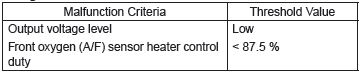
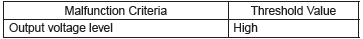
Detect front oxygen (A/F) sensor heater open or short circuit.
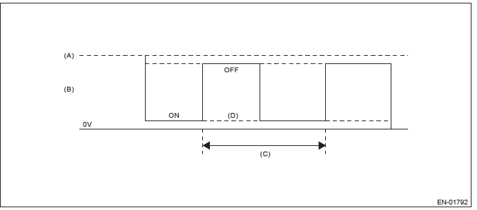
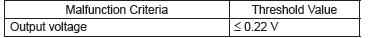
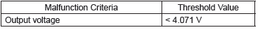
The front oxygen (A/F) sensor heater performs duty control, and the output terminal voltage at ON is 0 V, and the output terminal voltage at OFF is the battery voltage.
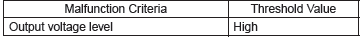
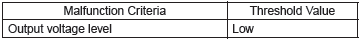
Judge as NG when the terminal voltage remains Low.
2. COMPONENT DESCRIPTION
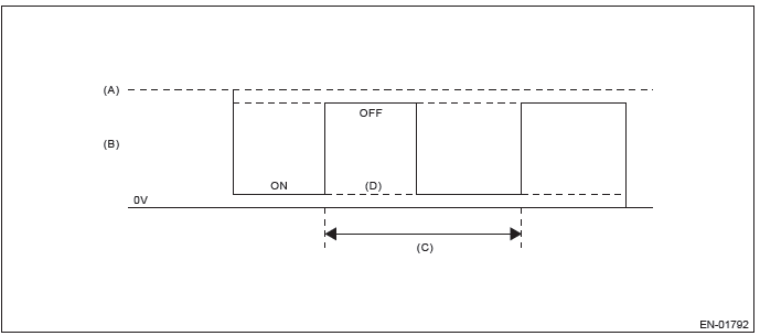
- Battery voltage
- Front oxygen (A/F) sensor heater output voltage
- 128 ms
- Low error
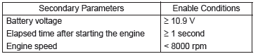
3. ENABLE CONDITION
4. GENERAL DRIVING CYCLE
Always perform the diagnosis continuously.
5. DIAGNOSTIC METHOD
- Abnormality Judgment
If the duration of time while the following conditions are met is longer than the time indicated, judge as NG.
Judgment Value
Time Needed for Diagnosis: 4 ms × 250 time(s)
Malfunction Indicator Light Illumination: Illuminates as soon as a malfunction
occurs.
- Normality Judgment
Judge as OK and clear the NG if the continuous time while the following conditions are established is more than the predetermined time.
Judgment Value
Time Needed for Diagnosis: Less than 1 second
E: DTC P0032 HO2S HEATER CONTROL CIRCUIT HIGH (BANK 1 SENSOR 1)
1. OUTLINE OF DIAGNOSIS
Detect front oxygen (A/F) sensor heater open or short circuit.
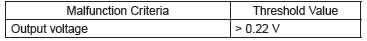
The front oxygen (A/F) sensor heater performs duty control, and the output terminal voltage at ON is 0 V, and the output terminal voltage at OFF is the battery voltage.
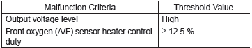
Judge as NG when the terminal voltage remains High.
2. COMPONENT DESCRIPTION
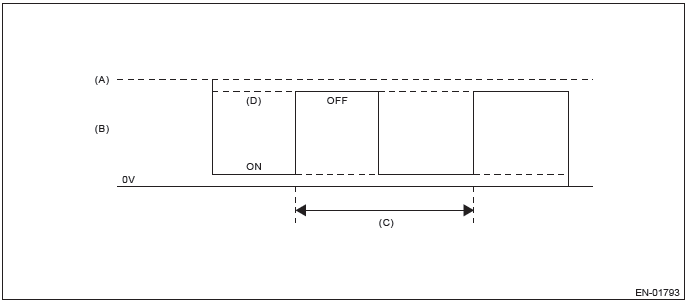
- Battery voltage
- Front oxygen (A/F) sensor heater output voltage
- 128 ms
- High error
3. ENABLE CONDITION
4. GENERAL DRIVING CYCLE
Always perform the diagnosis continuously.
5. DIAGNOSTIC METHOD
- Abnormality Judgment
If the duration of time while the following conditions are met is longer than the time indicated, judge as NG.
Judgment Value
Time Needed for Diagnosis: 4 ms × 500 time(s)
Malfunction Indicator Light Illumination: Illuminates as soon as a malfunction
occurs.
- Normality Judgment
Judge as OK and clear the NG if the continuous time while the following conditions are established is more than the predetermined time.
Judgment Value
Time Needed for Diagnosis: Less than 1 second
F: DTC P0037 HO2S HEATER CONTROL CIRCUIT LOW (BANK 1 SENSOR 2)
1. OUTLINE OF DIAGNOSIS
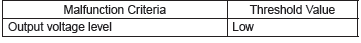
Detect the rear oxygen sensor heater open or short circuit.
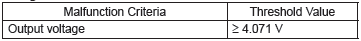
The rear oxygen sensor heater performs duty control, and the output terminal voltage at ON is 0 V, and the output terminal voltage at OFF is the battery voltage.
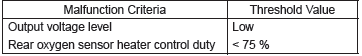
Judge as NG when the terminal voltage remains Low.
2. COMPONENT DESCRIPTION
- Battery voltage
- Output voltage of the rear oxygen sensor heater
- 256 ms (cycle)
- Low error
3. ENABLE CONDITION
4. GENERAL DRIVING CYCLE
After starting the engine, perform the diagnosis continuously when engine is low speed.
5. DIAGNOSTIC METHOD
- Abnormality Judgment
If the duration of time while the following conditions are met is longer than the time indicated, judge as NG.
Judgment Value
Time Needed for Diagnosis: 8 ms × 1250 time(s)
Malfunction Indicator Light Illumination: Illuminates when malfunction occurs in
2 continuous driving cycles.
- Normality Judgment
Judge as OK and clear the NG if the continuous time while the following conditions are established is more than the predetermined time.
Judgment Value
Time Needed for Diagnosis: Less than 1 second
G: DTC P0038 HO2S HEATER CONTROL CIRCUIT HIGH (BANK 1 SENSOR 2)
1. OUTLINE OF DIAGNOSIS
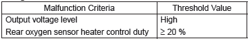
Detect the rear oxygen sensor heater open or short circuit.
The rear oxygen sensor heater performs duty control, and the output terminal voltage at ON is 0 V, and the output terminal voltage at OFF is the battery voltage.
Judge as NG when the terminal voltage remains High.
2. COMPONENT DESCRIPTION

- Battery voltage
- Output voltage of the rear oxygen sensor heater
- 256 ms (cycle)
- High error
3. ENABLE CONDITION
4. GENERAL DRIVING CYCLE
After starting the engine, perform the diagnosis continuously when engine is low speed.
5. DIAGNOSTIC METHOD
- Abnormality Judgment
If the duration of time while the following conditions are met is longer than the time indicated, judge as NG.
Judgment Value
Time Needed for Diagnosis: 8 ms × 1250 time(s)
Malfunction Indicator Light Illumination: Illuminates when malfunction occurs in
2 continuous driving cycles.
- Normality Judgment
Judge as OK and clear the NG if the continuous time while the following conditions are established is more than the predetermined time.
Judgment Value
Time Needed for Diagnosis: Less than 1 second
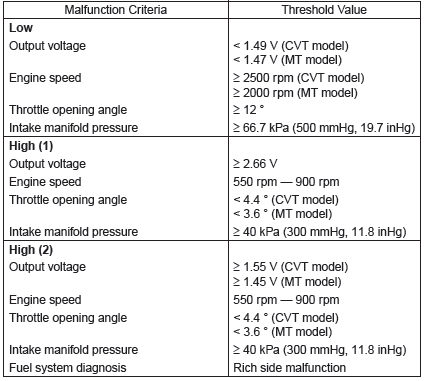
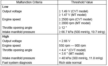
H: DTC P0068 MAP/MAF - THROTTLE POSITION CORRELATION
1. OUTLINE OF DIAGNOSIS
Detect problems in the intake manifold pressure sensor output properties.
Judge as NG when the intake air pressure AD value is Low whereas it seemed to be High from the viewpoint of engine condition, or when it is High whereas it seemed to be Low from the engine condition.
2. COMPONENT DESCRIPTION
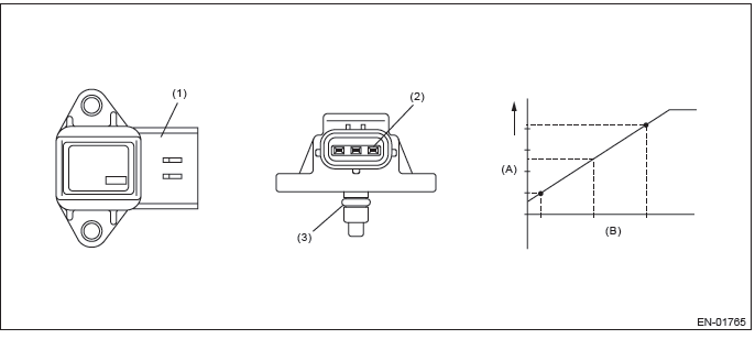
- Output voltage
- Absolute pressure
- Connector
- Terminals
- O-ring
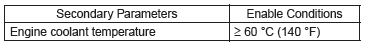
3. ENABLE CONDITION
4. GENERAL DRIVING CYCLE
Perform the diagnosis continuously after idling.
5. DIAGNOSTIC METHOD
- Abnormality Judgment
Judge as NG when Low side or High side becomes NG.
If the duration of time while the following conditions are met is longer than the time indicated, judge as NG.
Judgment Value
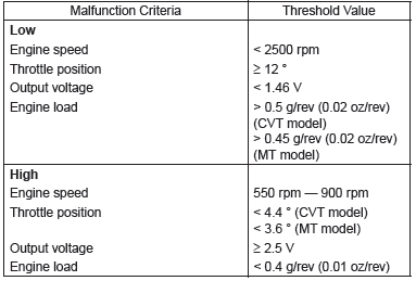
Time Needed for Diagnosis:
Low side: 5000 ms
High side: 5000 ms
Malfunction Indicator Light Illumination: Illuminates when malfunction occurs in 2 continuous driving cycles.
- Normality Judgment
Judge as OK and clear the NG when both Low side and High side become OK.
If the duration of time while the following conditions are met is longer than the time indicated, judge as OK.
Judgment Value
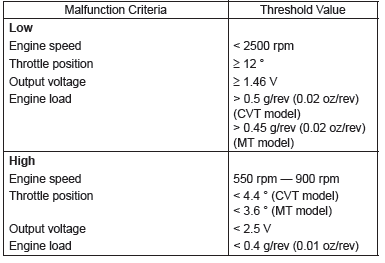
Time Needed for Diagnosis:
Low side: Less than 1 second
High side: Less than 1 second
I: DTC P0076 INTAKE VALVE CONTROL SOLENOID CIRCUIT LOW (BANK 1)
1. OUTLINE OF DIAGNOSIS
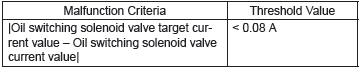
Detect the open circuit of the oil switching solenoid valve.
Judge as NG when the current is small even though the output duty is large.
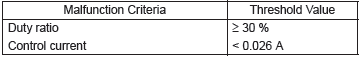
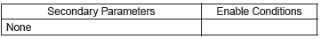
2. ENABLE CONDITION
3. GENERAL DRIVING CYCLE
Always perform the diagnosis continuously.
4. DIAGNOSTIC METHOD
- Abnormality Judgment
If the duration of time while the following conditions are met is longer than the time indicated, judge as NG.
Judgment Value
Time Needed for Diagnosis: 2000 ms
Malfunction Indicator Light Illumination: Illuminates as soon as a malfunction
occurs.
- Normality Judgment
Judge as OK and clear the NG if the continuous time while the following conditions are established is more than the predetermined time.
Judgment Value
Time Needed for Diagnosis: 2000 ms
J: DTC P0077 INTAKE VALVE CONTROL SOLENOID CIRCUIT HIGH (BANK 1)
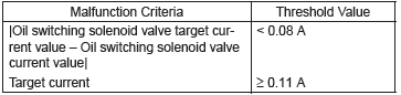
1. OUTLINE OF DIAGNOSIS
Detect short circuits of the oil switching solenoid valve.
Judge as a short NG when the current is large even though the output duty is small.
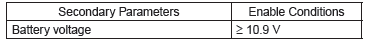
2. ENABLE CONDITION
3. GENERAL DRIVING CYCLE
Always perform the diagnosis continuously.
4. DIAGNOSTIC METHOD
- Abnormality Judgment
If the duration of time while the following conditions are met is longer than the time indicated, judge as NG.
Judgment Value
Time Needed for Diagnosis: 2000 ms
Malfunction Indicator Light Illumination: Illuminates as soon as a malfunction
occurs.
- Normality Judgment
Judge as OK and clear the NG if the continuous time while the following conditions are established is more than the predetermined time.
Judgment Value
Time Needed for Diagnosis: 2000 ms
K: DTC P0082 INTAKE VALVE CONTROL SOLENOID CIRCUIT LOW (BANK 2)
1. OUTLINE OF DIAGNOSIS
NOTE: For the detection standard, refer to DTC P0076. <Ref. to GD(H4SO)-23, DTC P0076 INTAKE VALVE CONTROL SOLENOID CIRCUIT LOW (BANK 1), Diagnostic Trouble Code (DTC) Detecting Criteria.>
L: DTC P0083 INTAKE VALVE CONTROL SOLENOID CIRCUIT HIGH (BANK 2)
1. OUTLINE OF DIAGNOSIS
NOTE: For the detection standard, refer to DTC P0077. <Ref. to GD(H4SO)-24, DTC P0077 INTAKE VALVE CONTROL SOLENOID CIRCUIT HIGH (BANK 1), Diagnostic Trouble Code (DTC) Detecting Criteria.>
M: DTC P0101 MASS OR VOLUME AIR FLOW CIRCUIT RANGE/PERFORMANCE
1. OUTLINE OF DIAGNOSIS
Detect the malfunction of air flow sensor output properties.
Judge as a low side NG when the air flow voltage indicates a small value regardless of running in a state where the air flow voltage increases. Judge as a high side NG when the air flow voltage indicates a large value regardless of running in a state where the air flow voltage decreases. Judge air flow sensor property NG when the Low side or High side becomes NG.
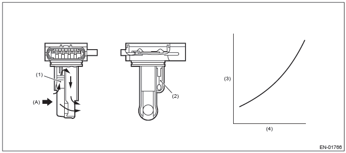
2. COMPONENT DESCRIPTION
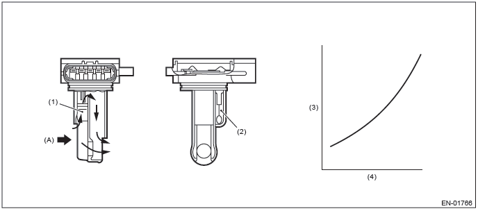
- Air
- Air flow sensor
- Intake air temperature sensor
- Voltage (V)
- Amount of intake air (kg (lb)/s)
3. ENABLE CONDITION
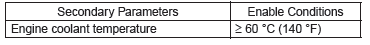
4. GENERAL DRIVING CYCLE
Perform the diagnosis continuously after idling.
5. DIAGNOSTIC METHOD
- Abnormality Judgment
Judge as NG when Low side or High side becomes NG.
If the duration of time while the following conditions are met is longer than the time indicated, judge as NG.
Judgment Value
Time Needed for Diagnosis:
Low: 5000 ms
High: 5000 ms
Malfunction Indicator Light Illumination: Illuminates when malfunction occurs in 2 continuous driving cycles.
- Normality Judgment
Judge as OK and clear the NG when both Low side and High side become OK.
Judge as OK and clear the NG if the continuous time while the following conditions are established is more than the predetermined time.
Judgment Value
Time Needed for Diagnosis:
Low: Less than 1 second
High: Less than 1 second
N: DTC P0102 MASS OR VOLUME AIR FLOW CIRCUIT LOW INPUT
1. OUTLINE OF DIAGNOSIS
Detect open or short circuits of the air flow sensor.
Judge as NG if out of specification.
2. COMPONENT DESCRIPTION
- Air
- Air flow sensor
- Intake air temperature sensor
- Voltage (V)
- Amount of intake air (kg (lb)/s)
3. ENABLE CONDITION
4. GENERAL DRIVING CYCLE
Always perform the diagnosis continuously.
5. DIAGNOSTIC METHOD
- Abnormality Judgment
If the duration of time while the following conditions are met is longer than the time indicated, judge as NG.
Judgment Value
Time Needed for Diagnosis: 500 ms
Malfunction Indicator Light Illumination: Illuminates as soon as a malfunction
occurs.
- Normality Judgment
Judge as OK and clear the NG if the continuous time while the following conditions are established is more than the predetermined time.
Judgment Value
Time Needed for Diagnosis: Less than 1 second
O: DTC P0103 MASS OR VOLUME AIR FLOW CIRCUIT HIGH INPUT
1. OUTLINE OF DIAGNOSIS
Detect open or short circuits of the air flow sensor.
Judge as NG if out of specification.
2. COMPONENT DESCRIPTION

- Air
- Air flow sensor
- Intake air temperature sensor
- Voltage (V)
- Amount of intake air (kg (lb)/s)
3. ENABLE CONDITION
4. GENERAL DRIVING CYCLE
Always perform the diagnosis continuously.
5. DIAGNOSTIC METHOD
- Abnormality Judgment
If the duration of time while the following conditions are met is longer than the time indicated, judge as NG.
Judgment Value
Time Needed for Diagnosis: 500 ms
Malfunction Indicator Light Illumination: Illuminates as soon as a malfunction
occurs.
- Normality Judgment
Judge as OK and clear the NG if the continuous time while the following conditions are established is more than the predetermined time.
Judgment Value
Time Needed for Diagnosis: Less than 1 second
READ NEXT:
 DTC P0107, P0108, P0111, P0112, P0113, P0117, P0118, P0122, P0123, P0125,
P0126, P0128
DTC P0107, P0108, P0111, P0112, P0113, P0117, P0118, P0122, P0123, P0125,
P0126, P0128
P: DTC P0107 MANIFOLD ABSOLUTE PRESSURE/BAROMETRIC PRESSURE
CIRCUIT LOW INPUT
1. OUTLINE OF DIAGNOSIS
Detect the open or short circuit of intake manifold pressure sensor.
Judge as NG if out of specif
DTC P0131, P0132, P0133, P0134, P0137, P0138, P013A, P013B, P013E, P013F,
P0140, P0141, P014C, P014D, P015A, P015B
AB:DTC P0131 O2 SENSOR CIRCUIT LOW VOLTAGE (BANK 1 SENSOR 1)
1. OUTLINE OF DIAGNOSIS
Detect the open or short circuit of sensor.
Judge as NG, when the element voltage is out of the specified range.
2
DTC P0171, P0172, P0181, P0182, P0183, P0196, P0197, P0198, P0201, P0202,
P0203, P0204, P0222, P0223, P0301, P0302, P0303, P0304
AR:DTC P0171 SYSTEM TOO LEAN (BANK 1)
1. OUTLINE OF DIAGNOSIS
Detect fuel system malfunction by the amount of main feedback control.
Diagnostic method
Fuel system is diagnosed by comparing the target
SEE MORE:
Rear Door
A: REMOVAL
1) Disconnect the ground cable from battery.
2) Remove the rear door trim. <Ref. to EI-61, REAR DOOR, REMOVAL, Door Trim.>
3) Remove the rear door speaker assembly.
Remove the screws.
Disconnect the harness connector and remove the rear speaker assembly.
4) Remove the rear se
ABS warning light
The ABS warning light illuminates when the ignition switch is turned to the “ON”
position and turns off after approximately 2 seconds.
This is an indication that the ABS system is working properly.
CAUTION
● If any of the following conditions occur, we recommend that you have the AB
