Subaru Outback manuals

Subaru Outback: ECO gauge

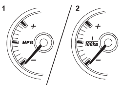
1) U.S.-spec. models


1) U.S.-spec. models
2) Except U.S.-spec. models

The ECO gauge shows the difference between the average rate of fuel consumption and the current rate of fuel consumption. Using the average rate of fuel consumption since the trip meter was last reset, the indicator needle behaves as described in the following items.

U.S.-spec. models:

If the current rate of fuel consumption is lower than the average rate of fuel consumption, the indicator needle points to the “+” side. If the current rate of fuel consumption is higher than the average rate of fuel consumption, the indicator needle points to the “−” side. When the indicator needle is pointing to the “+” side, it indicates fuel-efficient driving.

Except U.S.-spec. models:

If the current rate of fuel consumption is lower than the average rate of fuel consumption, the indicator needle points to the “−” side. If the current rate of fuel consumption is higher than the average rate of fuel consumption, the indicator needle points to the “+” side. When the indicator needle is pointing to the “−” side, it indicates fuel-efficient driving.

NOTE

● The ECO gauge shows only an approximate indication.

● After resetting the trip meter, the average rate of fuel consumption is not shown until driving 0.6 mile (1 km). Until that time, the ECO gauge does not operate.

READ NEXT:

 Warning and indicator lights

Several of the warning and indicator lights illuminate momentarily and then go out when the ignition switch is initially turned to the “ON” position. This permits checking the operation of the

 Seatbelt warning light and chime

Your vehicle is equipped with a seatbelt warning device at the driver’s and front passenger’s seat, as required by current safety standards. With the ignition switch turned to the “ON” posi

 Operation

If the driver and/or front passenger have/ has not yet fastened the seatbelt(s) when the ignition switch is turned to the “ON” position, the seatbelt warning light(s) will flash for 6 seconds,

SEE MORE:

 Air Conditioning System

A: WIRING DIAGRAM Refer to "Air Conditioning System" in the wiring diagram. <Ref. to WI-53, WIRING DIAGRAM, Air Conditioning System.> B: ELECTRICAL SPECIFICATION Refer to "Auto A/C Control Module I/O Signal" of "HVAC SYSTEM (DIAGNOSTICS)" section. <Ref. to AC(diag)- 6, ELECTRICAL SPECIFIC

 Front Differential Assembly

A: REMOVAL 1) Remove the manual transmission assembly from the vehicle. <Ref. to 6MT-25, REMOVAL, Manual Transmission Assembly.> 2) Remove the transfer case together with the extension case assembly. <Ref. to 6MT-40, REMOVAL, Transfer Case and Extension Case Assembly.> 3) Remove the tr

© 2010-2023 Copyright www.suoutback.com