Subaru Outback (BR): Front Ball Joint
A: REMOVAL
1) Lift up the vehicle, and then remove the front wheels.
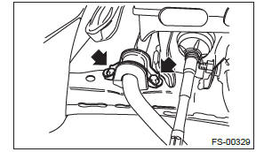
2) Remove the left and right stabilizer brackets.
3) Remove the ball joint.
- Extract the cotter pin (a) from the ball stud.
- Remove the castle nut (b).
- Extract the ball stud from the front arm.
- Remove the bolt securing the ball joint to the front axle housing.
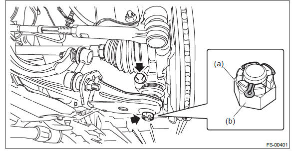
- Extract the ball joint from the front axle housing.
B: INSTALLATION
1) Install the ball joint to the front axle housing.
CAUTION:
- Do not apply grease to the tapered portion of ball stud.
- Before tightening, make sure the lower side of front axle housing and stepped section of ball joint are in contact.
- Lower side of front axle housing
- Raised section of ball joint
- Front axle housing
- Ball joint
Tightening torque: 50 N*m (5.1 kgf-m, 36.9 ft-lb)
2) Install the ball joint into front arm.
- Connect the ball joint to the front arm.
Tightening torque: 39 N*m (3.98 kgf-m, 28.8 ft-lb)
- Retighten the castle nut further up to 60º until the hole in the ball stud is aligned with a slot in castle nut.
- Insert a new cotter pin and bend it around the castle nut.
3) Install the stabilizer bracket.
NOTE: The stabilizer bracket has a set orientation. Install it with the arrow mark facing the upper side of the vehicle.
- Front side of vehicle
Tightening torque: 25 N*m (2.55 kgf-m, 18.4 ft-lb)
C: INSPECTION
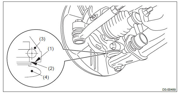
1) Measure the play of the ball joint using the following procedures. Replace with a new part if the play exceeds specification.
- With 686 N (70 kgf, 154 lbf) loaded in direction shown in the figure,
measure the length
 1.
1.
- With 686 N (70 kgf, 154 lbf) loaded in direction shown in the figure,
measure the length
 2.
2.
- Determine free play using the following formula.
S =
 2 -1
2 -1 - Replace with a new part if the play exceeds specification.
Front ball joint
Replacement standard S: Less than 0.3 mm (0.012 in)
2) If the play is within specification, visually check the dust cover.
3) If the dust cover is damaged, replace with a new ball joint.
READ NEXT:
 Front Arm
A: REMOVAL
1) Lift up the vehicle, and then remove the front wheels.
2) Remove the front arm.
Remove the nut and disconnect the front stabilizer link.
Remove the bolt, and then remove the ball joi
Front Strut
A: REMOVAL
1) Lift up the vehicle, and then remove the front wheels.
2) Remove the front strut.
Place an alignment mark on the camber adjusting bolt and strut.
Remove the brake hose bracket.
R
SEE MORE:
General Description of Vehicle Dynamics Control
A: SPECIFICATION
B: COMPONENT
1. ABS WHEEL SPEED SENSOR
Front ABS wheel speed sensor
Front axle housing
Rear ABS wheel speed sensor
Rear axle housing
Hub unit bearing
Magnetic encoder
Tightening torque:N*m (kgf-m, ft-lb)
T: 7.5 (0.76, 5.5)
2. STEERING ANGLE
Jump starting
WARNING
● Battery fluid is SULFURIC ACID. Do not let it come in contact with the eyes,
skin, clothing or the vehicle.
If battery fluid gets on you, thoroughly flush the exposed area with water immediately.
Get medical help if the fluid has entered your eyes.
If battery fluid is accident
