Subaru Outback (BR): Front Lateral Link
A: REMOVAL
1) Lift up the vehicle, and then remove the rear wheels.
2) Remove the trailing link.
- Remove the bracket, and remove the parking brake cable from the guide (a).
- Remove the bolts and nuts, and then remove the trailing link.
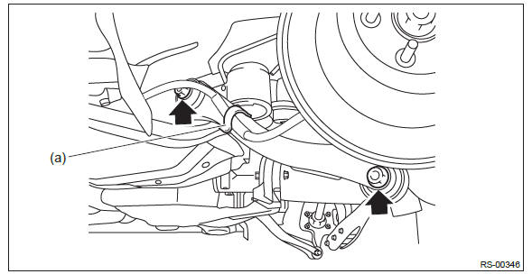
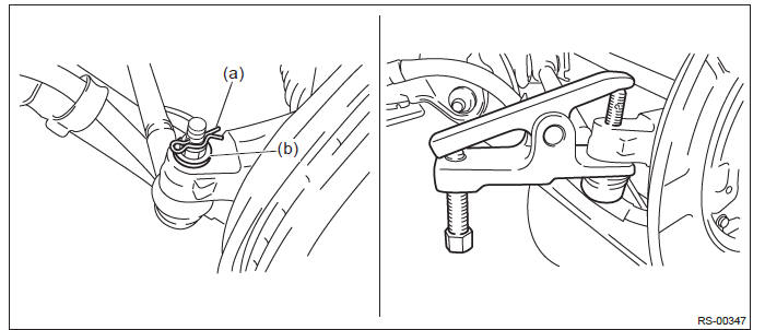
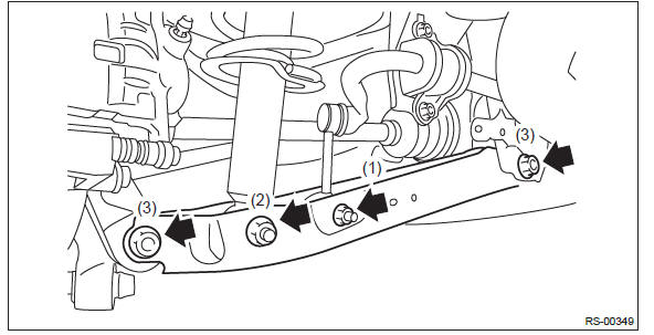
3) Remove the front lateral link.
- Remove the snap pin (a) and nut (b).
- Using a puller, remove the ball joint.
PREPARATION TOOL: Tie-rod end puller
- Scribe an alignment mark on the front lateral link adjusting bolt and rear sub frame.
- Remove the adjusting bolt, and remove the front lateral link.
CAUTION: When removing the adjusting bolt, make sure to fix the bolt head in place when loosening the nut.
B: INSTALLATION
CAUTION:
- Be sure to use a new self-locking nut.
- Always tighten the bushing in the state where the vehicle is at curb weight and the wheels are in full contact with the ground.
1) Before installation, inspect the following items and replace any faulty part with a new one.
- Visually check the front lateral link for damage and deformation.
- Visually check the bushing for abnormal cracks, fatigue or damage.
- Visually check the dust cover on the ball joint for abnormal cracks, fatigue or damage.
2) Install each part in the reverse order of removal.
Tightening torque:
Front lateral link - sub frame: 120 N*m (12.24 kgf-m, 88.5 ft-lb)
Front lateral link - rear axle housing: 60 N*m (6.12 kgf-m, 44.3 ft-lb)
3) Inspect the wheel alignment and adjust if necessary. <Ref. to FS-9, INSPECTION, Wheel Alignment.>
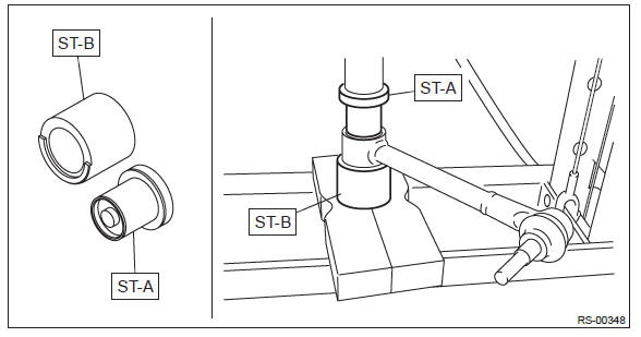
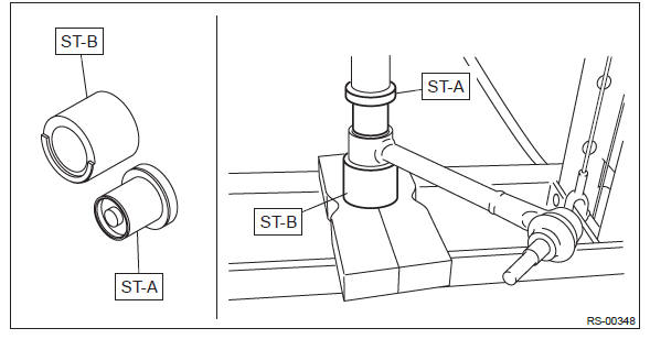
C: DISASSEMBLY
Using the ST, push out the bushing.
PREPARATION TOOL: ST-A & ST-B: INSTALLER & REMOVER (20299AE000)
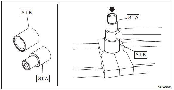
D: ASSEMBLY
1) Before assembly, inspect the following items and replace any faulty part with a new one.
- Visually check the front lateral link for damage and deformation.
- Visually check the bushing for abnormal cracks, fatigue or damage.
- Visually check the dust cover on the ball joint for damage.
2) Using the ST, press the bushing into place.
CAUTION: Make sure to press the bushing straight in.
PREPARATION TOOL: ST-A & ST-B: INSTALLER & REMOVER (20299AE000)
Rear Lateral Link
A: REMOVAL
1) Lift up the vehicle, and then remove the rear wheels.
2) Remove the bolts and nuts and lower the rear lateral link.
- Remove the nut and disconnect the rear stabilizer link.
- Remove the shock absorber lower bolt.
- Disconnect the rear lateral link.
B: INSTALLATION
CAUTION:
- Be sure to use a new self-locking nut.
- Always tighten the bushing in the state where the vehicle is at curb weight and the wheels are in full contact with the ground.
1) Before installation, inspect the following items and replace any faulty part with a new one.
- Visually check the rear lateral link for damage and deformation.
- Visually check the bushing for abnormal cracks, fatigue or damage.
2) Install each part in the reverse order of removal.
Tightening torque:
Rear lateral link: 80 N*m (8.16 kgf-m, 59.0 ft-lb)
Shock absorber: 80 N*m (8.16 kgf-m, 59.0 ft-lb)
Stabilizer link: 33 N*m (3.36 kgf-m, 24.3 ft-lb)
3) Inspect the wheel alignment and adjust if necessary. <Ref. to FS-9, INSPECTION, Wheel Alignment.>
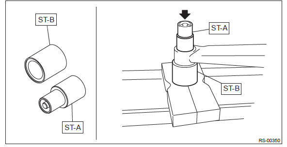
C: DISASSEMBLY
Using the ST, push out the bushing.
PREPARATION TOOL: ST-A & ST-B: INSTALLER & REMOVER (20299AE010)
D: ASSEMBLY
1) Before assembly, inspect the following items and replace any faulty part with a new one.
- Visually check the rear lateral link for damage and deformation.
- Visually check the bushing for abnormal cracks, fatigue or damage.
2) Using the ST, press the bushing into place.
PREPARATION TOOL: ST-A & ST-B: INSTALLER & REMOVER (20299AE010)
General Diagnostic Table
A: INSPECTION
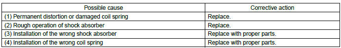
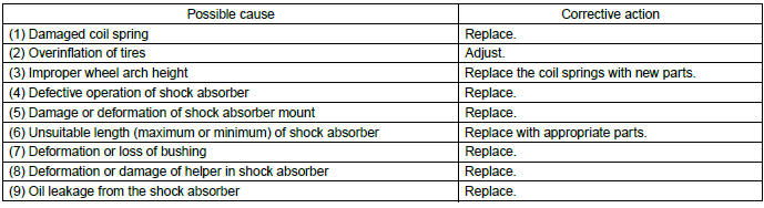
1. IMPROPER VEHICLE POSTURE OR IMPROPER WHEEL ARCH HEIGHT
2. POOR RIDE COMFORT
1) Large rebound shock
2) Rocking of the vehicle continues too long after running over bump and hump.
3) Excessive shock in bumping
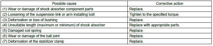
3. NOISE
READ NEXT:
 Wheel and Tire System
General Description
A: SPECIFICATION
Offset
P.C.D.
NOTE:
Size and inflation pressure of the standard equipment tire and spare tire for
emergency are described on the "Tire inflation pressure" l
Tire Pressure Monitoring System (Diagnostics)
Basic Diagnostic Procedure
A: PROCEDURE
CAUTION:
Before removal or installation, be sure to remove any foreign matter (dust,
moisture, oil, etc.) from
the TPMS & keyless entry control module conn
SEE MORE:
Tail/Stop Light Bulb
A: REMOVAL
1. SEDAN MODEL
Rear combination light side
1) Disconnect the ground cable from battery.
2) Release the lock and remove the bulb inspection cover of trunk room trim.
3) Remove the bulb socket and tail light/stop light bulb.
Rear finisher light side
1) Disconnect the ground cable f
ATF Cooler Pipe and Hose
A: REMOVAL
1) Remove the collector cover.
NOTE:
Follow the steps below when removing the collector
cover.
Pull up the two points at the rear (A).
Pull up the two points at the front (B) while
moving them forward.
2) Remove the battery.
3) Lift up the vehicle.
4) Remove the under cover. <R
