Subaru Outback (BR): General Description of Mechanical
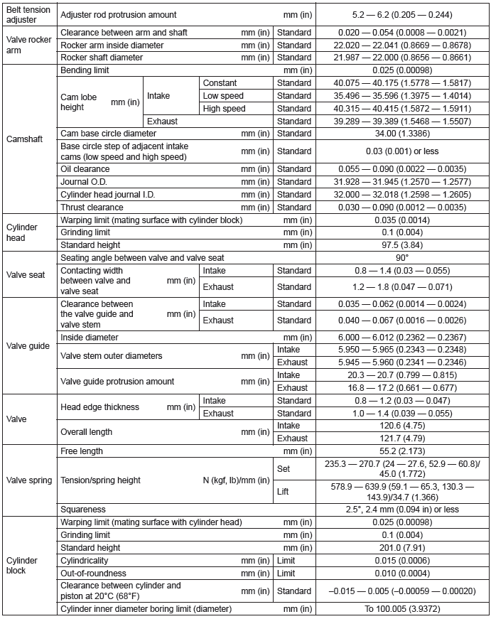
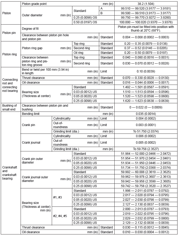
A: SPECIFICATION
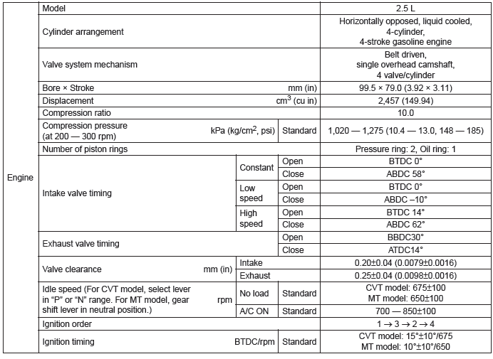
NOTE:
US: Undersize OS: Oversize
B: COMPONENT
1. V-BELT
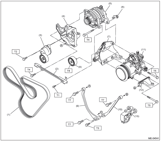
- V-belt
- V-belt cover bracket
- V-belt tensioner ASSY
- Power steering pump bracket
- Generator
- Generator plate
- A/C compressor bracket A
- Idler pulley ASSY
- Stopper rod RH
- Stopper rod LH
- A/C compressor
- A/C compressor bracket B
- Front cushion rubber
Tightening torque: N*m (kgf-m, ft-lb)
T1: 6.4 (0.7, 4.7)
T2: 20 (2.0, 14.8)
T4: 25 (2.5, 18.4)
T5: 26.5 (2.7, 19.5)
T6: 33 (3.4, 24.3)
T7: 36 (3.7, 26.6)
2. TIMING BELT
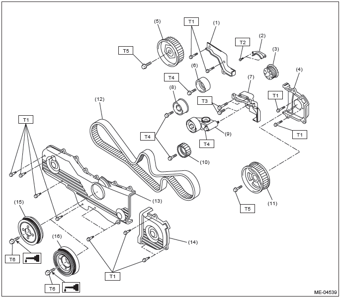
- Timing belt cover No. 2 RH
- Timing belt guide (MT model)
- Crank sprocket
- Timing belt cover No. 2 LH
- Cam sprocket No. 1
- Belt idler (A)
- Tensioner bracket
- Belt idler (B)
- Automatic belt tension adjuster ASSY
- Belt idler No. 2
- Cam sprocket No. 2
- Timing belt
- Front timing belt cover
- Timing belt cover LH
- Crank pulley (MT model)
- Crank pulley (CVT model)
Tightening torque: N*m (kgf-m, ft-lb)
T1: 5 (0.5, 3.7)
T2: 9.75 (1.0, 7.2)
T3: 24.5 (2.5, 18.1)
T4: 39 (4.0, 28.8)
T5: 78 (8.0, 57.5)
T6: <Ref. to ME(H4SO)-45, INSTALLATION, Crank Pulley.>
3. CYLINDER HEAD AND CAMSHAFT
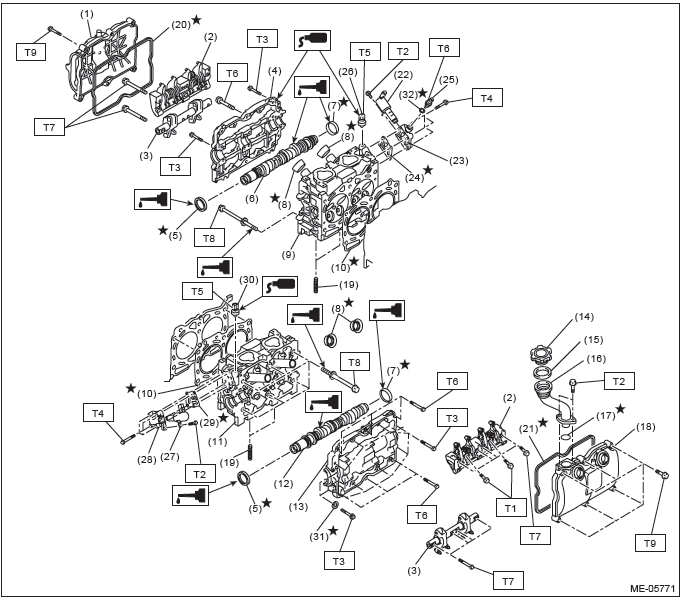
- Rocker cover RH
- Intake valve rocker ASSY
- Exhaust valve rocker ASSY
- Camshaft cap RH
- Oil seal
- Camshaft RH
- Plug
- Spark plug pipe gasket
- Cylinder head RH
- Cylinder head gasket
- Cylinder head LH
- Camshaft LH
- Camshaft cap LH
- Oil filler cap
- Gasket
- Oil filler duct
- O-ring
- Rocker cover LH
- Stud bolt
- Rocker cover gasket RH
- Rocker cover gasket LH
- Oil switching solenoid valve RH
- Oil switching solenoid valve holder RH
- Gasket
- Oil temperature sensor
- Variable valve lift diagnosis oil pressure switch RH
- Oil switching solenoid valve LH
- Oil switching solenoid valve holder LH
- Gasket
- Variable valve lift diagnosis oil pressure switch LH
- Seal washer
- Washer
Tightening torque: N*m (kgf-m, ft-lb)
T1: 6 (0.6, 4.4)
T2: 6.4 (0.7, 4.7)
T3: 9.75 (1.0, 7.2)
T4: 10 (1.0, 7.4)
T5: 17 (1.7, 12.5)
T6: 18 (1.8, 13.3)
T7: 25 (2.5, 18.4)
T8: <Ref. to ME(H4SO)-63, INSTALLATION, Cylinder Head.>
T9: <Ref. to ME(H4SO)-55, INSTALLATION, Valve Rocker Assembly.>
4. VALVE ROCKER ASSY
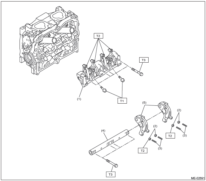
- Intake valve rocker ASSY
- Valve rocker nut
- Valve rocker adjusting screw
- Exhaust rocker shaft
- Exhaust valve rocker arm
Tightening torque: N*m (kgf-m, ft-lb)
T1: 6 (0.6, 4.4)
T2: 9.75 (1.0, 7.2)
T3: 25 (2.5, 18.4)
5. CYLINDER HEAD AND VALVE ASSEMBLY
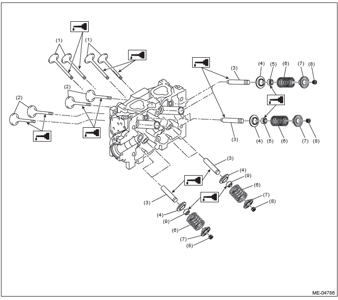
- Exhaust valve
- Intake valve
- Valve guide
- Valve spring seat
- Intake valve oil seal
- Valve spring
- Valve spring retainer
- Valve spring retainer key
- Exhaust valve oil seal
6. CYLINDER BLOCK
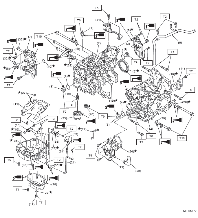
- Oil pressure switch
- Cylinder block RH
- Service hole plug
- Gasket
- Oil separator cover
- Water by-pass pipe
- Oil pump
- Front oil seal
- Rear oil seal
- O-ring
- Service hole cover
- Cylinder block LH
- Water pump
- Baffle plate
- Oil filter connector
- Oil strainer
- Cylinder block lower
- Oil pan
- Drain plug
- Drain plug gasket
- Oil level gauge guide
- Water pump sealing
- Oil filter
- Gasket
- Water pump hose
- Plug
- Seal
- Seal washer
- Washer
- O-ring
- Engine rear hanger
- Oil pump seal
- Oil level gauge
- O-ring
- O-ring
- Oil drain pipe
- O-ring
- Oil level switch
Tightening torque: N*m (kgf-m, ft-lb)
T1: 5 (0.5, 3.7)
T2: 6.4 (0.7, 4.7)
T3: 10 (1.0, 7.4)
T4: First 12 (1.2, 8.9)
Second 12 (1.2, 8.9)
T5: 16 (1.6, 11.8)
T6: 25 (2.5, 18.4)
T7: 41.7 (4.3, 30.8)
T8: 45 (4.6, 33.2)
T9: 70 (7.1, 51.6)
T10: <Ref. to ME(H4SO)-76, INSTALLATION, Cylinder Block.>
7. CRANKSHAFT AND PISTON
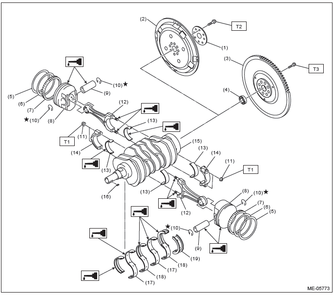
- Reinforcement (CVT model)
- Drive plate (CVT model)
- Flywheel (MT model)
- Ball bearing (MT model)
- Top ring
- Second ring
- Oil ring
- Piston
- Piston pin
- Snap ring
- Connecting rod nut
- Connecting rod
- Connecting rod bearing
- Connecting rod cap
- Crankshaft
- Woodruff key
- Crankshaft bearing #1, #3
- Crankshaft bearing #2, #4
- Crankshaft bearing #5
Tightening torque: N*m (kgf-m, ft-lb)
T1: 45 (4.6, 33.2)
T2: <Ref. to CVT-133, INSTALLATION, Drive Plate.>
T3: <Ref. to CL-14, INSTALLATION, Flywheel.>
8. ENGINE MOUNTING
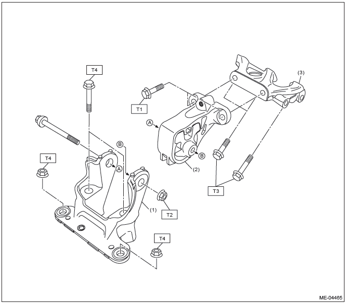
- Front mounting bracket
- Front cushion rubber
- Engine mounting bracket
Tightening torque: N*m (kgf-m, ft-lb)
T1: 25 (2.5, 18.4)
T2: 45 (4.6, 33.2)
T3: 58 (5.9, 42.8)
T4: 60 (6.1, 44.3)
C: CAUTION
- Wear appropriate work clothing, including a cap, protective goggles and protective shoes when performing any work.
- Remove contamination including dirt and corrosion before removal, installation or disassembly.
- Keep the disassembled parts in order and protect them from dust and dirt.
- Before removal, installation or disassembly, be sure to clarify the failure. Avoid unnecessary removal, installation, disassembly and replacement.
- Vehicle components are extremely hot after driving. Be wary of receiving burns from heated parts.
- Be sure to tighten fasteners including bolts and nuts to the specified torque.
- Place shop jacks or rigid racks at the specified points.
- Before disconnecting connectors of sensors or units, be sure to disconnect the ground cable from the battery.
- All parts should be thoroughly cleaned, paying special attention to engine oil passages, pistons and bearings.
- Rotating parts and sliding parts such as piston, bearing and gear should be coated with oil prior to assembly.
- Be careful not to let oil, grease or coolant contact the timing belt, clutch disc and flywheel.
- All removed parts, if to be reused, should be reinstalled in the original positions and directions.
- Bolts, nuts and washers should be replaced with new parts as required.
- Even if necessary inspections have been made in advance, proceed with assembly work while making rechecks.
- Remove or install the engine in an area where chain hoists, lifting devices, etc. are available for ready use.
- Be sure not to damage coated surfaces of body panels with tools, or not to stain seats and windows with coolant or oil. Place a cover over fender, as required, for protection.
- Prior to starting work, prepare the following: Service tools, clean cloth, containers to catch coolant and oil, wire ropes, chain hoist, transmission jacks, etc.
- Lift up or lower the vehicle when necessary. Make sure to support the correct positions.
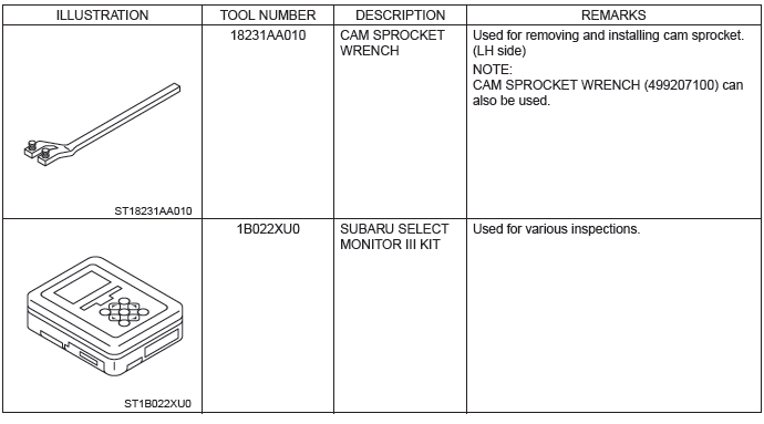
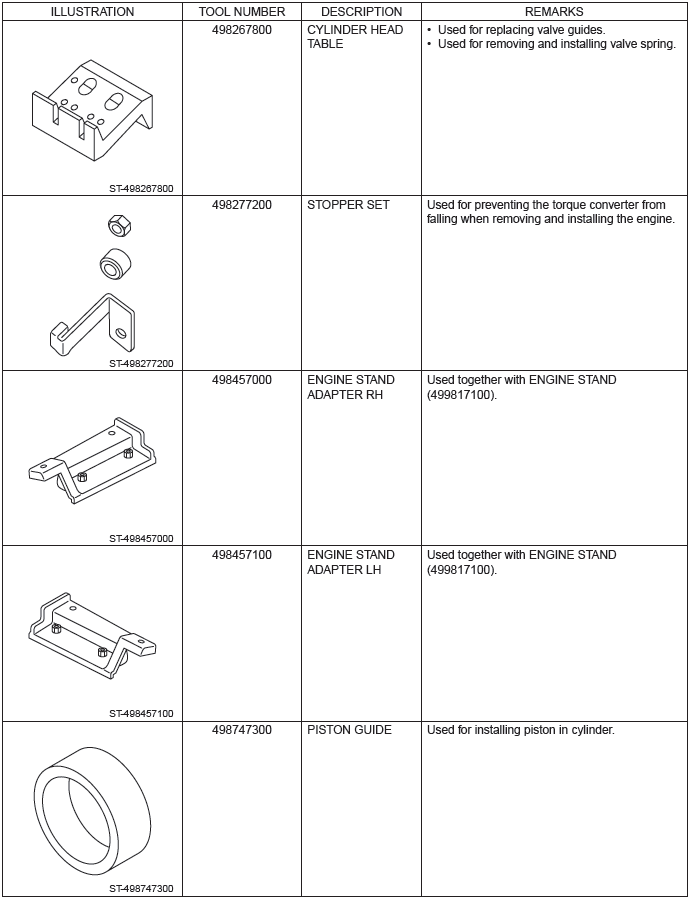
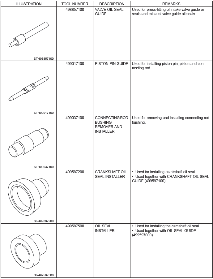
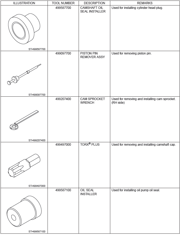
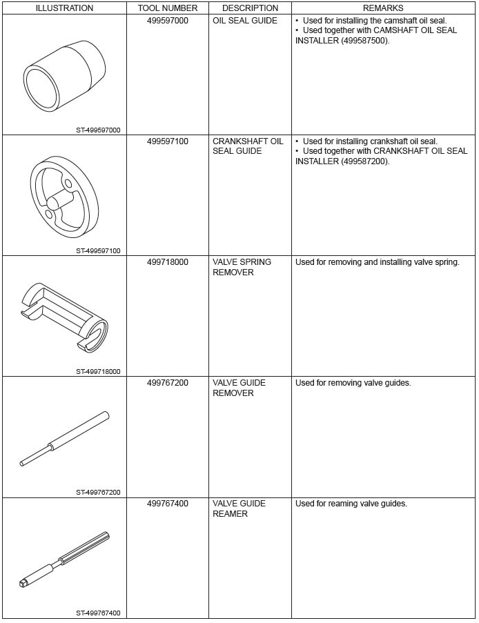
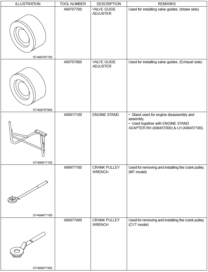
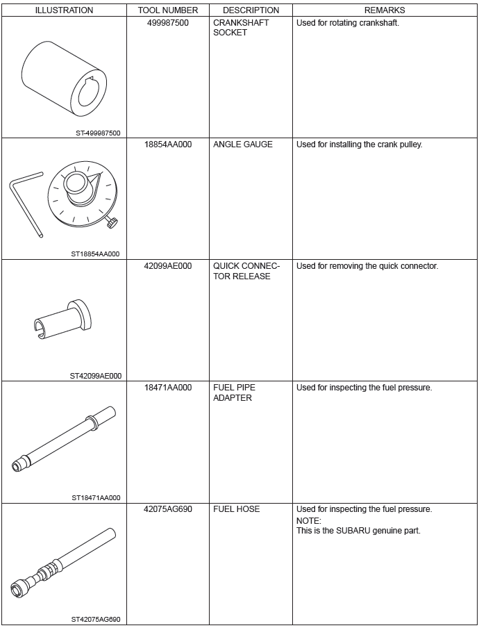
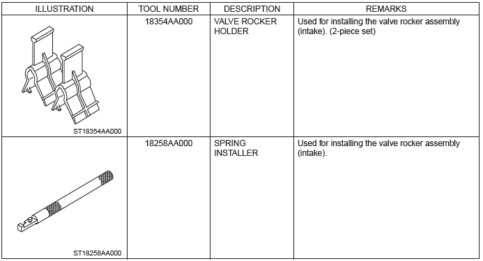
D: PREPARATION TOOL
1. SPECIAL TOOL
2. GENERAL TOOL
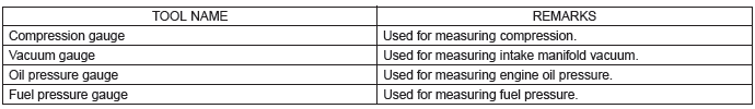
Compression
A: INSPECTION
CAUTION: After warming-up, engine becomes very hot. Be careful not to burn yourself during measurement.
1) After warming-up the engine, turn the ignition switch to OFF.
2) Make sure that the battery is fully charged.
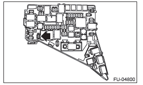
3) Remove the fuse of fuel pump from main fuse box.
4) Start the engine and run it until it stalls.
5) After the engine stalls, crank it for five more seconds.
6) Turn the ignition switch to OFF.
7) Remove all spark plugs. <Ref. to IG(H4SO)-3, REMOVAL, Spark Plug.>
8) Fully open the throttle valve.
9) Check the starter motor for satisfactory performance and operation.
10) Install the compression gauge to the spark plug hole.
NOTE: When using a screw-in type compression gauge, the screw should be less than 18 mm (0.71 in) long.
11) Crank the engine by starter motor and read the value when the needle of the compression gauge becomes stable.
NOTE:
- Perform at least two measurements per cylinder, and make sure that the values are correct.
- If the compression pressure is out of standard, check or adjust the pistons, valves and cylinders.
Compression (fully open throttle):
Standard
1,020 - 1,275 kPa (10.4 - 13.0 kgf/cm2, 148 - 185 psi)
Difference between cylinders
49 kPa (0.5 kgf/cm2, 7 psi) or less
12) After inspection, install the related parts in the reverse order of removal.
Idle Speed
A: INSPECTION
1) Before checking the idle speed, check the following item:
- Check the air cleaner element is free from clogging, ignition timing is correct, spark plugs are in good condition, and hoses are connected properly.
- Check the malfunction indicator light does not illuminate.
2) Warm up the engine.
3) Read the engine idle speed using Subaru Select Monitor. <Ref. to EN(H4SO)(diag)-33, READ CURRENT DATA FOR ENGINE (NORMAL MODE), OPERATION, Subaru Select Monitor.>
NOTE:
- Idle speed cannot be adjusted manually, because the idle speed is automatically adjusted.
- If idle speed is out of standard, refer to the General Diagnosis Table under "Engine Control System".
<Ref. to EN(H4SO)(diag)-2, Basic Diagnostic Procedure.>
- Check the idle speed when no-loaded.
(Headlight, heater fan, rear defroster, radiator fan, A/C and etc. are OFF)
Idle speed (No load, and for CVT model, select lever in "P" or "N" range, for MT model, gear shift lever in neutral position.):
Standard
675+-100 rpm (CVT model)
650+-100 rpm (MT model)
- Check the idle speed when loaded. (Turn the A/C switch to "ON" and operate the compressor for at least one minute before measurement.)
Idle speed (A/C on, and for CVT model, select lever in "P" or "N" range, for MT model, gear shift lever in neutral position.):
Standard
700 - 850+-100 rpm
Ignition Timing
A: INSPECTION
CAUTION: After warming-up, engine becomes very hot. Be careful not to burn yourself at measurement.
1) Before checking the ignition timing, check the following item:
- Check the air cleaner element is free from clogging, spark plugs are in good condition, and hoses are connected properly.
- Check the malfunction indicator light does not illuminate.
2) Warm up the engine.
3) Read the ignition timing using Subaru Select Monitor. <Ref. to EN(H4SO)(diag)-33, READ CURRENT DATA FOR ENGINE (NORMAL MODE), OPERATION, Subaru Select Monitor.>
NOTE: If ignition timing is out of standard, check the ignition control system. Refer to "Engine Control System".
<Ref. to EN(H4SO)(diag)-2, Basic Diagnostic Procedure.>
Ignition timing [BTDC/rpm]:
Standard
15º+-10º/675 (CVT model)
10º+-10º/650 (MT model)
Intake Manifold Vacuum
A: INSPECTION
1) Warm up the engine.
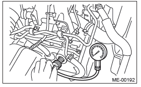
2) Disconnect the brake booster vacuum hose from the intake manifold, and attach the vacuum gauge.
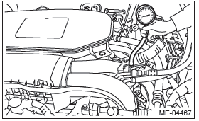
3) Keep the engine at idle speed and read the vacuum gauge indication.
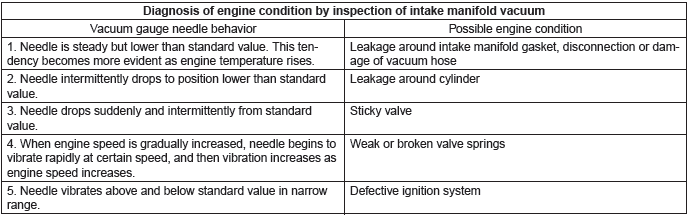
NOTE: Condition of engine inside can be diagnosed by observing the behavior of the vacuum gauge needle as described in table below.
Intake manifold vacuum (at idling, A/C OFF):
Standard
-60.0 kPa (-450 mmHg, -17.72 inHg) or more
4) After inspection, install the related parts in the reverse order of removal.
Engine Oil Pressure
A: INSPECTION
1) Disconnect the ground cable from battery.
2) Remove the oil pressure switch. <Ref. to LU(H4SO)-25, REMOVAL, Oil Pressure Switch.>
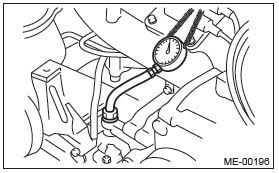
3) Install the oil pressure gauge to cylinder block.
4) Connect the battery ground terminal.
5) Start the engine, and check the oil pressure.
NOTE:
- Standard value is based on an engine oil temperature of 80ºC (176ºF).
- If the oil pressure is out of specification, check oil pump, oil filter and lubrication line. <Ref. to LU(H4SO)-45, INSPECTION, Engine Lubrication System Trouble in General.>
- If the oil pressure warning light is ON and oil pressure is within specification, check the oil pressure switch. <Ref. to LU(H4SO)-45, INSPECTION, Engine Lubrication System Trouble in General.>
Engine oil pressure:
Standard
98 kPa (1.0 kgf/cm2, 14 psi) or more (at 600 rpm)
294 kPa (3.0 kgf/cm2, 43 psi) or more (at 5,000 rpm)
6) After inspection, install the related parts in the reverse order of removal.
Fuel Pressure
A: INSPECTION
CAUTION:
- Before removing the fuel pressure gauge, release the fuel pressure.
- Be careful not to spill fuel.
- Catch the fuel from hoses using a container or cloth.
1) Release the fuel pressure. <Ref. to FU(H4SO)- 53, RELEASING OF FUEL PRESSURE, PROCEDURE, Fuel.>
2) Open the fuel filler lid and remove the fuel filler cap.
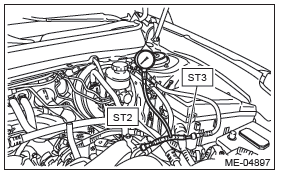
3) Disconnect the fuel delivery hose from the fuel delivery pipe, and connect the fuel pressure gauge.
CAUTION:
- Be careful not to spill fuel.
- Catch the fuel from hoses using a container or cloth.
- Attach ST to the fuel delivery pipe and push ST1 in the direction of arrow mark to disconnect the quick connector of the fuel delivery hose.
ST 42099AE000 QUICK CONNECTOR RELEASE
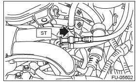
- Connect the fuel pressure gauge with ST2 and ST3.
NOTE:
ST2 is a SUBARU genuine part.
ST2 42075AG690 FUEL HOSE
ST3 18471AA000 FUEL PIPE ADAPTER
4) Start the engine.
5) Check the fuel pressure after warming up the engine.
NOTE:
- The fuel pressure gauge registers 10 to 20 kPa (0.1 to 0.2 kgf/cm2, 1 to 3 psi) higher than standard values during high-altitude operations.
- Check or replace the fuel pump and fuel delivery line if the fuel pressure is out of the standard.
Fuel pressure:
Standard
340 - 400 kPa (3.5 - 4.1 kgf/cm2, 49 - 58 psi)
6) After inspection, install the related parts in the reverse order of removal.
Valve Clearance
A: INSPECTION
CAUTION: If engine oil is spilt onto the exhaust pipe, wipe it off with cloth to avoid emission of smoke or causing a fire.
NOTE: Inspection of valve clearance should be performed while engine is cold.
1) Lift up the vehicle.
2) Remove the under cover. <Ref. to EI-35, REMOVAL, Front Under Cover.>
3) Lower the vehicle.
4) Disconnect the ground cable from battery.
5) Remove the timing belt cover LH.
6) Remove the fuel injector. <Ref. to FU(H4SO)- 37, REMOVAL, Fuel Injector.>
7) When inspecting #1 and #3 cylinders
- Disconnect the ignition coil from spark plug on RH side. <Ref. to IG(H4SO)-3, RH SIDE, REMOVAL, Spark Plug.>
- Place a suitable container under the vehicle.
- Disconnect the PCV hose from the rocker cover RH.
- Remove the bolts, then remove the rocker cover RH.
8) When inspecting #2 and #4 cylinders
- Disconnect the ignition coil from spark plug on LH side. <Ref. to IG(H4SO)-3, LH SIDE, REMOVAL, Spark Plug.>
- Place a suitable container under the vehicle.
- Disconnect the PCV hose from the rocker cover LH.
- Remove the bolts, then remove the rocker cover LH.
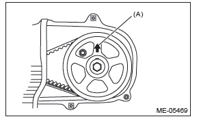
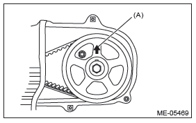
9) Set #1 cylinder piston to top dead center of compression stroke by rotating the crank pulley clockwise using the socket wrench.
NOTE: When the arrow mark (A) on cam sprocket LH is at the top position, the #1 cylinder piston is at top dead center of the compression stroke.
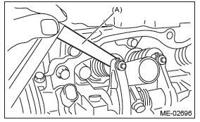
10) Measure #1 cylinder valve clearance by using thickness gauge (A).
NOTE:
- Insert the thickness gauge (A) in as horizontally as possible with respect to the valve stem end face.
- Lift up the vehicle, and then measure the exhaust valve clearances.
- If the measured value is not within the inspection value, take notes of the value in order to adjust the valve clearance later on.
Valve clearance (inspection value):
Intake
0.20+-0.04 mm (0.0079+-0.0016 in)
Exhaust
0.25+-0.04 mm (0.0098+-0.0016 in)
11) Measure the valve clearance in #3, #2 and #4 cylinder in the same measurement procedure as #1 cylinder in this order.
NOTE:
- Be sure to set the cylinder pistons to their respective top dead centers on compression stroke before measuring valve clearances.
- By rotating the crank pulley clockwise every 180º from the state that #1 cylinder piston is on the top dead center of compression stroke, #3, #2 and #4 cylinder pistons come to the top dead center of compression stroke in this order.
12) If necessary, adjust the valve clearance. <Ref. to ME(H4SO)-30, ADJUSTMENT, Valve Clearance.>
13) After inspection, install the related parts in the reverse order of removal.
NOTE: Refer to "Camshaft" when installing the rocker cover. <Ref. to ME(H4SO)-59, INSTALLATION, Camshaft.>
B: ADJUSTMENT
CAUTION: If engine oil is spilt onto the exhaust pipe, wipe it off with cloth to avoid emission of smoke or causing a fire.
NOTE: Adjustment of valve clearance should be performed while engine is cold.
1) Set #1 cylinder piston to top dead center of compression stroke by rotating the crank pulley clockwise using the socket wrench.
NOTE: When the arrow mark (A) on cam sprocket LH is at the top position, the #1 cylinder piston is at top dead center of the compression stroke.
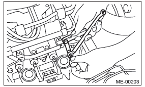
2) Adjust the #1 cylinder valve clearance.
- Loosen the valve rocker nut and screw.
- Set a suitable thickness gauge.
- While noting the valve clearance, tighten the valve rocker adjusting screw.
- When the specified valve clearance is obtained, tighten the valve rocker nut.
NOTE:
- Insert a thickness gauge in a direction as horizontal as possible with respect to the valve stem end face.
- Lift up the vehicle and adjust the exhaust valve clearances.
Valve clearance (adjustment value):
Intake
0.20+-0.04 mm (0.0079+-0.0016 in)
Exhaust
0.25+-0.04 mm (0.0098+-0.0016 in)
Tightening torque:
9.75 N*m (1.0 kgf-m, 7.2 ft-lb)
3) Adjust the valve clearance in #3, #2 and #4 cylinder in the same adjustment procedure as #1 cylinder in this order.
NOTE:
- Be sure to set the cylinder pistons to their respective top dead centers on compression stroke before adjusting valve clearances.
- By rotating the crank pulley clockwise every 180º from the state that #1 cylinder piston is on the top dead center of compression stroke, #3, #2 and #4 cylinder pistons come to the top dead center of compression stroke in this order.
4) Ensure the valve clearances of each cylinder are within specifications. If necessary, readjust the valve clearances.
5) After adjustment, install the related parts in the reverse order of removal.
NOTE: Refer to "Camshaft" when installing the rocker cover.
<Ref. to ME(H4SO)-59, INSTALLATION, Camshaft.>
READ NEXT:
 Engine Assembly
A: REMOVAL
1) Change the front hood damper mounting position
from (A) to (B), and completely open the front
hood.
Tightening torque:
20 N*m (2.0 kgf-m, 14.8 ft-lb)
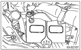
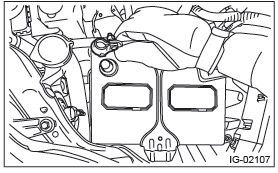
2) Remove the V-belt covers.
3) C
Engine Mounting
A: REMOVAL
1) Change the front hood damper mounting position
from (A) to (B), and completely open the front
hood.
Tightening torque:
20 N*m (2.0 kgf-m, 14.8 ft-lb)
2) Disconnect the ground cable from
Timing Belt Cover
A: REMOVAL
NOTE:
When replacing a single part, perform the work with
the engine assembly installed to body.
1) Remove the crank pulley. <Ref. to ME(H4SO)-
45, REMOVAL, Crank Pulley.>
2) Remove
SEE MORE:
Air cleaner element
WARNING
Do not operate the engine with the air cleaner element removed. The air cleaner
element not only filters intake air but also stops flames if the engine backfires.
If the air cleaner element is not installed when the engine backfires, you could
be burned.
CAUTION
When replacing the a
Drive Pinion Shaft Assembly in Continuously Variable Transmission
A: REMOVAL
1) Remove the transmission assembly from the vehicle. <Ref. to CVT-55, REMOVAL, Automatic Transmission Assembly.>
2) Remove the air breather hose. <Ref. to CVT-132, REMOVAL, Air Breather Hose.>
3) Remove the oil pan and control valve body. <Ref. to CVT-111, REMOVAL, Con
