Subaru Outback (BR): Timing Belt Cover
A: REMOVAL
NOTE: When replacing a single part, perform the work with the engine assembly installed to body.
1) Remove the crank pulley. <Ref. to ME(H4SO)- 45, REMOVAL, Crank Pulley.>
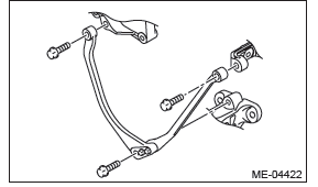
2) Remove the stopper rod.
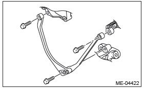
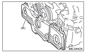
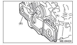
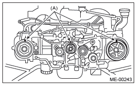
3) Remove the timing belt cover LH (A).
4) Remove the front timing belt cover (B).
B: INSTALLATION
1) Install the front timing belt cover (B).
Tightening torque: 5 N*m (0.5 kgf-m, 3.7 ft-lb)
2) Install the timing belt cover LH (A).
Tightening torque: 5 N*m (0.5 kgf-m, 3.7 ft-lb)
3) Install the stopper rod.
Tightening torque: 36 N*m (3.7 kgf-m, 26.6 ft-lb)
4) Install the crank pulley. <Ref. to ME(H4SO)-45, INSTALLATION, Crank Pulley.>
C: INSPECTION
Check that the timing belt cover does not have de- formation, cracks and any other damage.
Timing Belt
A: REMOVAL
NOTE:
- When replacing a single part, perform the work with the engine assembly installed to body.
- When performing the work with the engine installed
to body, the following parts must also be removed/
installed.
- Radiator main fan motor assembly <Ref. to CO(H4SO)-24, REMOVAL, Radiator Main Fan and Fan Motor.> <Ref. to CO(H4SO)-24, INSTALLATION, Radiator Main Fan and Fan Motor.>
- Radiator sub fan motor assembly <Ref. to CO(H4SO)-25, REMOVAL, Radiator Sub Fan and Fan Motor.> <Ref. to CO(H4SO)-25, INSTALLATION, Radiator Sub Fan and Fan Motor.>
- When performing the work with the engine installed to body, protect the radiator with cardboards or blankets.
1. TIMING BELT
1) Remove the crank pulley. <Ref. to ME(H4SO)- 45, REMOVAL, Crank Pulley.>
2) Remove the timing belt cover. <Ref. to ME(H4SO)-47, REMOVAL, Timing Belt Cover.>
3) Remove the timing belt guide. (MT model)
4) If the alignment mark or arrow mark (which indicates the direction of rotation) on timing belt fade away, put new marks before removing the timing belt as shown in procedures below.
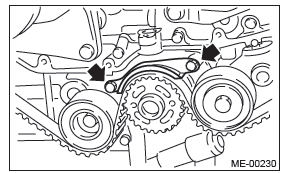
- Use the ST to turn crankshaft. Align the mark (a) of sprocket to the mark (b) of oil pump, and then ensure the right side cam sprocket mark (c), cam cap and cylinder head matching surface (d) or left side cam sprocket mark (e), timing belt cover notch (f) are properly adjusted.
ST 499987500 CRANKSHAFT SOCKET
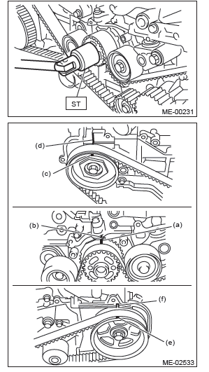
- Using white paint, put an alignment mark or an arrow mark on timing belts in relation to the crank sprocket and cam sprockets.
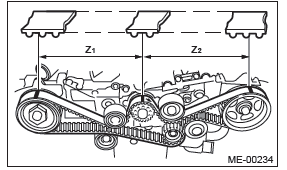
Z1: 46.8 teeth
Z2: 43.7 teeth
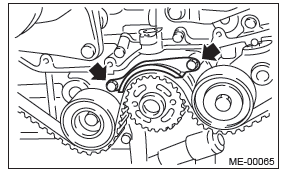
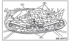
5) Remove the belt idler (A).
6) Remove the belt idler No. 2 (B).
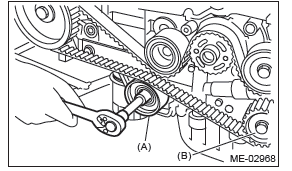
7) Remove the timing belt.
2. BELT IDLER AND AUTOMATIC BELT TENSION ADJUSTER ASSEMBLY
1) Remove the belt idler.
2) Remove the automatic belt tension adjuster assembly.
B: INSTALLATION
1. AUTOMATIC BELT TENSION ADJUSTER ASSEMBLY AND BELT IDLER
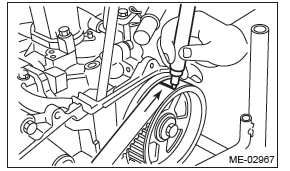
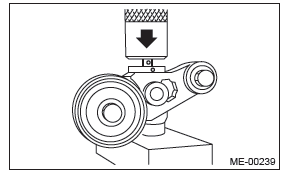
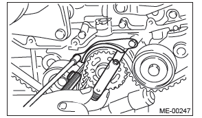
1) Prepare for installation of the automatic belt tension adjuster assembly.
CAUTION:
- Always use a vertical type pressing tool to move the adjuster rod down.
- Do not use a lateral type vise.
- Push the adjuster rod vertically.
- Press-in the push adjuster rod gradually taking three minutes or more.
- Do not allow press pressure to exceed 9,807 N (1,000 kgf, 2,205 lb).
- Push in the adjuster rod to the end face of the cylinder. However, do not push in the adjuster rod below the end face of the cylinder. Doing so may damage the cylinder.
- Do not release the press pressure until stopper pin is completely inserted.
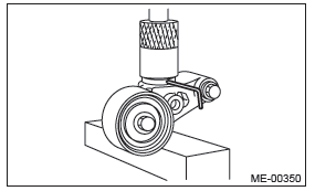
- Attach the automatic belt tension adjuster assembly to vertical pressing tool.
- Slowly push in the adjuster rod with a pressure of 165 N (16.8 kgf, 37.1 lbf) or more until the adjuster rod is aligned with the stopper pin hole in the cylinder.
- With a 2 mm (0.08 in) dia. stopper pin or a 2 mm (nominal) dia. hex wrench inserted into the stopper pin hole in cylinder, secure the adjuster rod.
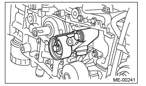
2) Install the automatic belt tension adjuster assembly.
Tightening torque: 39 N*m (4.0 kgf-m, 28.8 ft-lb)
3) Install the belt idlers.
Tightening torque: 39 N*m (4.0 kgf-m, 28.8 ft-lb)

2. TIMING BELT
1) Prepare for installation of the automatic belt tension adjuster assembly. <Ref. to ME(H4SO)-49, AUTOMATIC BELT TENSION ADJUSTER ASSEMBLY AND BELT IDLER, INSTALLATION, Timing Belt.>
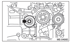
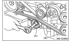
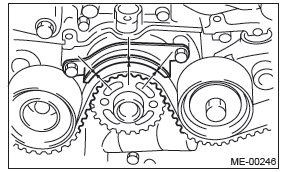
2) Align the mark (B) on oil pump with the mark (A) on crank sprocket.
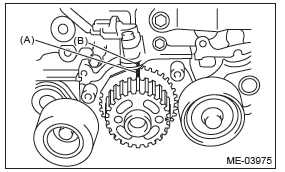
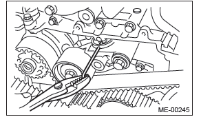
3) Turn the camshaft sprocket No. 2 using ST1, and turn the camshaft sprocket No. 1 using ST2 so that their alignment marks (A) come to top positions.
ST1 18231AA010 CAM SPROCKET WRENCH
NOTE: CAM SPROCKET WRENCH (499207100) can also be used.
ST2 499207400 CAM SPROCKET WRENCH
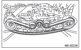
4) While aligning the alignment mark (B) on timing belt with the mark (A) on sprockets, position the timing belt properly.
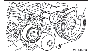
5) Install the belt idler No. 2 (B).
Tightening torque: 39 N*m (4.0 kgf-m, 28.8 ft-lb)
6) Install the belt idler (A).
Tightening torque: 39 N*m (4.0 kgf-m, 28.8 ft-lb)
7) After ensuring the marks on timing belt and camshaft sprockets are aligned, remove the stopper pin from belt tension adjuster.
8) Install the timing belt guide. (MT model)
- Temporarily tighten the bolts mounting the timing belt guide.
- Check and adjust the clearance between timing belt and timing belt guide by using thickness gauge.
Clearance: 1.0+-0.5 mm (0.039+-0.020 in)
- Tighten the bolts mounting the timing belt guide.
Tightening torque: 9.75 N*m (1.0 kgf-m, 7.2 ft-lb)
9) Install the timing belt cover. <Ref. to ME(H4SO)- 47, INSTALLATION, Timing Belt Cover.>
10) Install the crank pulley. <Ref. to ME(H4SO)-45, INSTALLATION, Crank Pulley.>
C: INSPECTION
1. TIMING BELT
1) Check the timing belt teeth for breaks, cracks or wear. If any fault is found, replace the timing belt.
2) Check the condition on the back surface of the timing belt. If cracks are found, replace the timing belt.
CAUTION:
- Be careful not to let oil, grease or coolant contact the timing belt. Remove quickly and thoroughly if this happens.
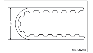
- Do not bend the timing belt sharply.
In radial diameter h: 60 mm (2.36 in) or more
2. AUTOMATIC BELT TENSION ADJUSTER
1) Visually check the oil seals for leaks, and rod ends for abnormal wear and scratches. If necessary, replace the automatic belt tension adjuster assembly.
NOTE: Slight traces of oil at rod's oil seal does not indicate a problem.
2) Check that the adjuster rod does not move when a pressure of 165 N (16.8 kgf, 37.1 lb) is applied to it. This is to check adjuster rod stiffness.
3) If the adjuster rod is not stiff and moves freely when applying 165 N (16.8 kgf, 37.1 lb), check it using the following procedures:
- Slowly press the adjuster rod down to the end surface of cylinder. Repeat this operation two to three times.
- With the adjuster rod moved all the way up, apply a pressure of 165 N (16.8 kgf, 37.1 lb) to it, and check the adjuster rod stiffness.
- If the adjuster rod is not stiff and moves down, replace the automatic belt tension adjuster assembly with a new part.
CAUTION:
- Always use a vertical type pressing tool to move the adjuster rod down.
- Do not use a lateral type vise.
- Push the adjuster rod vertically.
- Press the adjuster rod gradually taking three minutes or more.
- Do not allow press pressure to exceed 9,807 N (1,000 kgf, 2,205 lb).
- Push in the adjuster rod to the end face of the cylinder. However, do not press the adjuster rod below the end face of the cylinder. Doing so may damage the cylinder.
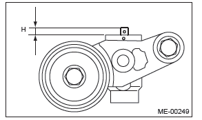
4) Measure the amount of adjuster rod protrusion "H" from the end surface of the cylinder. If it is not within specifications, replace the automatic belt tension adjuster assembly with a new part.
Amount of adjuster rod protrusion H: 5.2 - 6.2 mm (0.205 - 0.244 in)
3. BELT TENSION PULLEY
1) Check the mating surfaces of timing belt and contact point of adjuster rod for abnormal wear or scratches. Replace the automatic belt tension adjuster assembly with a new part if faulty.
2) Check the belt tension pulley for smooth rotation.
Replace the automatic belt tension adjuster assembly with a new part if abnormal noise or excessive play occurs.
3) Check the belt tension pulley for grease leakage.
4. BELT IDLER
1) Check the belt idler for smooth rotation. Replace if noise or excessive play occurs.
2) Check the outer contacting surfaces of idler pulley for abnormal wear and scratches.
3) Check the belt idler for grease leakage.
READ NEXT:
 Cam Sprocket
A: REMOVAL
NOTE:
When replacing a single part, perform the work with
the engine assembly installed to body.
1) Remove the crank pulley. <Ref. to ME(H4SO)-
45, REMOVAL, Crank Pulley.>
2) Remove
Cylinder Head
A: REMOVAL
NOTE:
When replacing a single part, perform the work
with the engine assembly installed to body. Refer to
"Valve Clearance" for preparation procedures.
<Ref. to ME(H4SO)-29, Valve C
Cylinder Block
A: REMOVAL
NOTE:
Before conducting this procedure, drain the engine
oil completely.
1) Remove the engine from the vehicle. <Ref. to
ME(H4SO)-31, REMOVAL, Engine Assembly.>
2) Remove the intake
SEE MORE:
Starter
A: REMOVAL
1) Disconnect the ground cable from battery.
2) Remove the cover (A) and clip (B) from air intake
boot assembly. (2.5 L non-turbo model)
3) Loosen the clamp (A) which connects the air intake
boot assembly and air cleaner case. (2.5 L
non-turbo model)
4) Loosen the clamp (B) which connec
Rear center seating position
CAUTION
The head restraint is not intended to be used at the lowest position. Before sitting on the seat, raise the head restraint to the extended position.
A) When not used (retracted position) B) When used (extended position)
1) Head restraint
2) Release button
To raise:
