Subaru Outback (BR): Cam Sprocket
A: REMOVAL
NOTE: When replacing a single part, perform the work with the engine assembly installed to body.
1) Remove the crank pulley. <Ref. to ME(H4SO)- 45, REMOVAL, Crank Pulley.>
2) Remove the timing belt cover. <Ref. to ME(H4SO)-47, REMOVAL, Timing Belt Cover.>
3) Remove the timing belt. <Ref. to ME(H4SO)-48, REMOVAL, Timing Belt.>
4) Remove the camshaft position sensor. <Ref. to FU(H4SO)-27, REMOVAL, Camshaft Position Sensor.>
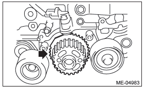
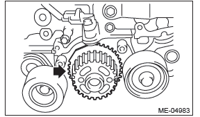
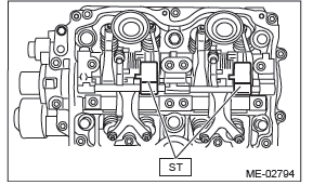
5) Use the ST to lock the cam sprocket, and remove the cam sprocket bolt.
ST 18231AA010 CAM SPROCKET WRENCH
NOTE: CAM SPROCKET WRENCH (499207100) can also be used.
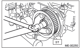
ST 499207400 CAM SPROCKET WRENCH
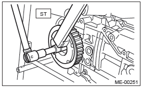
6) Remove the cam sprocket.
B: INSTALLATION
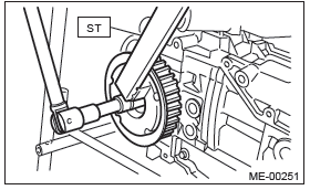
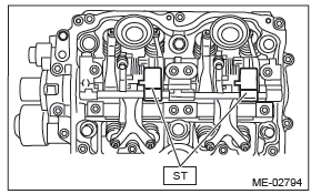
1) Install the cam sprocket.
2) Use the ST to lock the cam sprocket, and install the cam sprocket bolt.
NOTE:
- Do not confuse cam sprockets (LH) and (RH) during installation.
- They can be distinguished by the L or R indication.
ST 18231AA010 CAM SPROCKET WRENCH
NOTE: CAM SPROCKET WRENCH (499207100) can also be used.
Tightening torque: 78 N*m (8.0 kgf-m, 57.5 ft-lb)
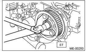
ST 499207400 CAM SPROCKET WRENCH
Tightening torque: 78 N*m (8.0 kgf-m, 57.5 ft-lb)
3) Install the camshaft position sensor. <Ref. to FU(H4SO)-27, INSTALLATION, Camshaft Position Sensor.>
4) Install the timing belt. <Ref. to ME(H4SO)-49, INSTALLATION, Timing Belt.>
5) Install the timing belt cover. <Ref. to ME(H4SO)- 47, INSTALLATION, Timing Belt Cover.>
6) Install the crank pulley. <Ref. to ME(H4SO)-45, INSTALLATION, Crank Pulley.>
C: INSPECTION
1) Check the cam sprocket teeth for abnormal wear and scratches.
2) Make sure there is no free play between cam sprocket and key.
3) Check the cam sprocket protrusion used for sensor for damage and contamination of foreign matter.
Crank Sprocket
A: REMOVAL
NOTE: When replacing a single part, perform the work with the engine assembly installed to body.
1) Remove the crank pulley. <Ref. to ME(H4SO)- 45, REMOVAL, Crank Pulley.>
2) Remove the timing belt cover. <Ref. to ME(H4SO)-47, REMOVAL, Timing Belt Cover.>
3) Remove the timing belt. <Ref. to ME(H4SO)-48, REMOVAL, Timing Belt.>
4) Remove the crank sprocket.
B: INSTALLATION
1) Install the crank sprocket.
2) Install the timing belt. <Ref. to ME(H4SO)-49, INSTALLATION, Timing Belt.>
3) Install the timing belt cover. <Ref. to ME(H4SO)- 47, INSTALLATION, Timing Belt Cover.>
4) Install the crank pulley. <Ref. to ME(H4SO)-45, INSTALLATION, Crank Pulley.>
C: INSPECTION
1) Check the crank sprocket teeth for abnormal wear and scratches.
2) Make sure there is no free play between crank sprocket and key.
3) Check the crank sprocket protrusion used for sensor for damage and contamination of foreign matter.
Valve Rocker Assembly
A: REMOVAL
NOTE: When replacing a single part, perform the work with the engine assembly installed to body. Refer to "Valve Clearance" for preparation procedures.
<Ref. to ME(H4SO)-29, Valve Clearance.>
1) Remove the ignition coil. <Ref. to IG(H4SO)-5, REMOVAL, Ignition Coil.>
2) Disconnect the PCV hose and remove the rocker cover.
3) Remove the valve rocker assembly.
- Use the ST to rotate the spring stopper in the direction of the arrow to remove it from adjuster pin.
ST 18258AA000 SPRING INSTALLER
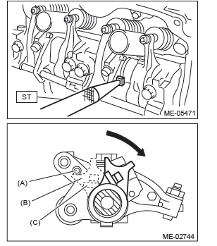
- Adjuster pin
- Spring stopper
- Spring
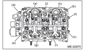
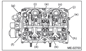
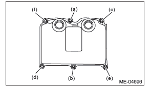
- Remove the bolts (a) through (j) in alphabetical sequence.
NOTE: Leave two or three threads of bolts (i) and (j) engaged in order to retain the valve rocker assembly.
- Remove the valve rocker assembly.
NOTE: Set the ST in the position shown in the drawing to remove the intake valve rocker assembly.
ST 18354AA000 VALVE ROCKER HOLDER
B: INSTALLATION
1) Install the valve rocker assembly.
- Temporarily tighten the bolts equally in alphabetical order as shown in the figure.
NOTE:
- Do not temporarily tighten the bolts (i) and (j).
- Set the ST in the position shown in the drawing to mount the intake valve rocker assembly.
ST 18354AA000 VALVE ROCKER HOLDER
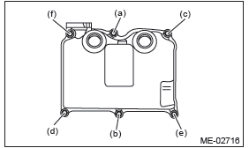
- Tighten the bolts (a) through (h) to specified torque.
Tightening torque: 25 N*m (2.5 kgf-m, 18.4 ft-lb)
- Tighten the bolts (i) through (j) to specified torque.
Tightening torque: 6 N*m (0.6 kgf-m, 4.4 ft-lb)
- Use the ST to rotate the spring stopper in the direction of the arrow to fasten the adjuster pin.
ST 18258AA000 SPRING INSTALLER
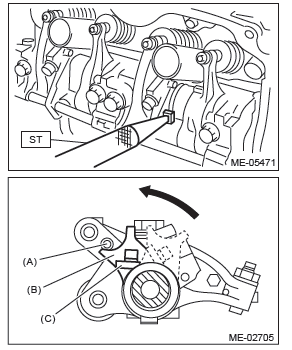
- Adjuster pin
- Spring stopper
- Spring
2) Remove the timing belt cover LH.
3) Adjust the valve clearance. <Ref. to ME(H4SO)- 30, ADJUSTMENT, Valve Clearance.>
4) Install the timing belt cover LH.
Tightening torque: 5 N*m (0.5 kgf-m, 3.7 ft-lb)
5) Install the rocker cover.
- Install the rocker cover gasket to the rocker cover.
NOTE: Use a new rocker cover gasket.
- Temporarily tighten the bolts in alphabetical order shown in the figure, tighten them in two stages.
Tightening torque:
First
6.4 N*m (0.7 kgf-m, 4.7 ft-lb)
Second (only (a) and (b) are tightened)
6.4 N*m (0.7 kgf-m, 4.7 ft-lb)
- RH side
- LH side
- Connect the PCV hose.
6) Install the ignition coil. <Ref. to IG(H4SO)-5, INSTALLATION, Ignition Coil.>
C: DISASSEMBLY
NOTE: Intake valve rocker assembly cannot be disassembled.
1) Remove the exhaust valve rocker arm from the rocker shaft.
NOTE: Keep all the removed parts in order for re-installing in their original positions.
2) Remove the nut and adjusting screw from exhaust valve rocker.
D: ASSEMBLY
NOTE: Intake valve rocker assembly cannot be disassembled.
1) Install the adjusting screw and nut to the exhaust valve rocker.
2) Insert the exhaust valve rocker arm to rocker shaft.
NOTE: Valve rocker arms, and rocker shaft have identification marks. Make sure the parts with same markings are properly assembled.
E: INSPECTION
1. INTAKE VALVE ROCKER ASSEMBLY
1) If the roller or valve contact surface of valve rocker arm is worn or dented excessively, replace the valve rocker assembly.
2) Check that the valve rocker arm roller rotates smoothly. If not, replace the valve rocker assembly.
2. EXHAUST VALVE ROCKER ASSEMBLY
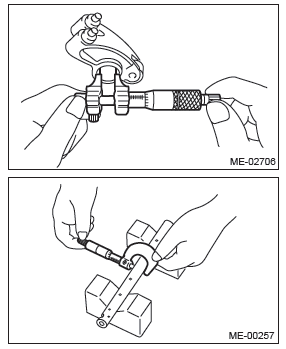
1) Measure the inner diameter of valve rocker arm and outer diameter of valve rocker shaft, and confirm the difference (oil clearance) between the two values.
Clearance between arm and shaft:
Standard
0.020 - 0.054 mm (0.0008 - 0.0021 in)
2) If the oil clearance exceeds the limit, replace the valve rocker arm or shaft, whichever shows the greater amount of wear.
Rocker arm inside diameter:
Standard
22.020 - 22.041 mm (0.8669 - 0.8678 in)
Rocker shaft diameter:
Standard
21.987 - 22.000 mm (0.8656 - 0.8661 in)
3) If the roller or valve contact surface of valve rocker arm is worn or dented excessively, replace the valve rocker arm.
4) Check that the valve rocker arm roller rotates smoothly. If not, replace the valve rocker arm.
READ NEXT:
 Cylinder Head
A: REMOVAL
NOTE:
When replacing a single part, perform the work
with the engine assembly installed to body. Refer to
"Valve Clearance" for preparation procedures.
<Ref. to ME(H4SO)-29, Valve C
Cylinder Block
A: REMOVAL
NOTE:
Before conducting this procedure, drain the engine
oil completely.
1) Remove the engine from the vehicle. <Ref. to
ME(H4SO)-31, REMOVAL, Engine Assembly.>
2) Remove the intake
Oil Switching Solenoid Valve
A: REMOVAL
1. RH SIDE
1) Disconnect the ground cable from battery.
2) Remove the cover (A) and clip (B) from air intake
boot assembly.
3) Loosen the clamp (A) which connects the air intake
boot asse
SEE MORE:
Double trip meter
1) Trip knob
This meter displays the two trip meters when the ignition switch is in the “ON”
position.
The trip meter shows the distance that the vehicle has been driven since you
last set it to zero.
If you press the trip knob when the ignition switch is in the “LOCK” or “Acc”
Front Speaker
A: REMOVAL
1. FRONT SIDE SPEAKER
1) Disconnect the ground cable from battery.
2) Remove the front side speaker.
Release the clips and claws, then detach the speaker cover.
CAUTION:
Use a plastic clip remover for removal.
Remove the screws.
Preparation tool: Stubby screwdriver
Disconnect the
