Subaru Outback (BR): Cylinder Head
A: REMOVAL
NOTE:
- When replacing a single part, perform the work with the engine assembly installed to body. Refer to "Valve Clearance" for preparation procedures. <Ref. to ME(H4SO)-29, Valve Clearance.>
- When performing the work with the engine installed to body, the following parts must also be removed/ installed.
Front exhaust pipe <Ref. to EX(H4SO)-5, REMOVAL, Front Exhaust Pipe.> <Ref. to EX(H4SO)-6, INSTALLATION, Front Exhaust Pipe.>
1) Remove the intake manifold. <Ref. to FU(H4SO)-17, REMOVAL, Intake Manifold.>
2) Remove the crank pulley. <Ref. to ME(H4SO)- 45, REMOVAL, Crank Pulley.>
3) Remove the timing belt cover. <Ref. to ME(H4SO)-47, REMOVAL, Timing Belt Cover.>
4) Remove the timing belt. <Ref. to ME(H4SO)-48, REMOVAL, Timing Belt.>
5) Remove the cam sprocket. <Ref. to ME(H4SO)- 53, REMOVAL, Cam Sprocket.>
6) Remove the bolts which secure A/C compressor bracket to cylinder head.
7) Remove the valve rocker assembly. <Ref. to ME(H4SO)-55, REMOVAL, Valve Rocker Assembly.>
8) Remove the camshaft. <Ref. to ME(H4SO)-58, REMOVAL, Camshaft.>
9) Remove the oil level gauge guide. (LH side)
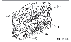
10) Remove the cylinder head bolts in alphabetical sequence as shown in the figure.
NOTE: Leave bolts (a) and (c) engaged by three or four threads to prevent the cylinder head from falling.
11) While tapping the cylinder head with a plastic hammer, separate it from cylinder block. Remove the bolts (a) and (c) to remove cylinder head.
12) Remove the cylinder head gasket.
CAUTION: Be careful not to scratch the mating surface of cylinder head and cylinder block.
13) Similarly, remove the right side cylinder head.
B: INSTALLATION
1) Install the cylinder head to the cylinder block.
CAUTION: Be careful not to scratch the mating surface of cylinder head and cylinder block.
NOTE: Use a new cylinder head gasket.
- Clean the bolt threads and the bolt holes in the cylinder block
CAUTION: To avoid erroneous tightening of the bolts, clean out the bolt holes sufficiently by blowing with compressed air to eliminate engine coolant etc.
- Apply a sufficient coat of engine oil to the washer and bolt thread.
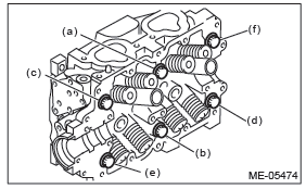
- Tighten all bolts to 40 N*m (4.1 kgf-m, 29.5 ft-lb) in alphabetical order.
- Retighten all bolts to 95 N*m (9.7 kgf-m, 70.1 ft-lb) in alphabetical order.
CAUTION: If the bolt makes stick-slip sound during tightening, repeat the procedure from step (1). In this case, the cylinder head gasket can be reused.
- Loosen all the bolts by 180º in the reverse order of installing, and loosen them further by 180º.
- Tighten all bolts to 10 N*m (1.0 kgf-m, 7.4 ftlb) in alphabetical order.
- Retighten all bolts to 30 N*m (3.1 kgf-m, 22.1 ft-lb) in alphabetical order.
- Retighten all bolts to 60 N*m (6.1 kgf-m, 44.3 ft-lb) in alphabetical order.
- Retighten all bolts by 80 - 90º in alphabetical order.
- Retighten all bolts by 40 - 45º in alphabetical order.
CAUTION: The tightening angle of the bolt should not exceed 45º.
- Retighten bolts (a) and (b) by 40 - 45º.
CAUTION: Make sure the total "tightening angle" of steps (10) and (11) does not exceed 90º.
2) Similarly, install the right side cylinder head.
3) Install the oil level gauge guide. (LH side)
Tightening torque: 6.4 N*m (0.7 kgf-m, 4.7 ft-lb)
4) Install the camshaft. <Ref. to ME(H4SO)-59, INSTALLATION, Camshaft.>
5) Install the valve rocker assembly. <Ref. to ME(H4SO)-55, INSTALLATION, Valve Rocker Assembly.>
6) Install the A/C compressor bracket on cylinder head.
Tightening torque: 36 N*m (3.7 kgf-m, 26.6 ft-lb)
7) Install the cam sprocket. <Ref. to ME(H4SO)-53, INSTALLATION, Cam Sprocket.>
8) Install the timing belt. <Ref. to ME(H4SO)-49, INSTALLATION, Timing Belt.>
9) Adjust the valve clearance. <Ref. to ME(H4SO)- 30, ADJUSTMENT, Valve Clearance.>
10) Install the rocker cover.
- Install the rocker cover gasket to the rocker cover.
NOTE: Use a new rocker cover gasket.
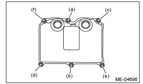
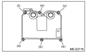
- Temporarily tighten the bolts in alphabetical order shown in the figure, tighten them in two stages.
Tightening torque:
First
6.4 N*m (0.7 kgf-m, 4.7 ft-lb)
Second (only (a) and (b) are tightened)
6.4 N*m (0.7 kgf-m, 4.7 ft-lb)
- RH side
- LH side
11) Install the timing belt cover. <Ref. to ME(H4SO)-47, INSTALLATION, Timing Belt Cover.>
12) Install the crank pulley. <Ref. to ME(H4SO)-45, INSTALLATION, Crank Pulley.>
13) Install the intake manifold. <Ref. to FU(H4SO)- 21, INSTALLATION, Intake Manifold.>
C: DISASSEMBLY
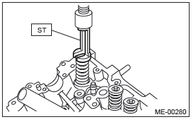
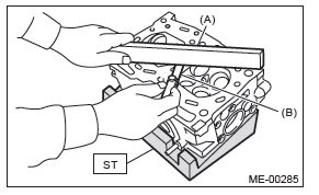
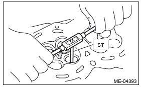
1) Place the cylinder head on the ST.
ST 498267800 CYLINDER HEAD TABLE 2) Compress the valve spring and remove the valve spring retainer key using ST. Remove each valve and valve spring.
ST 499718000 VALVE SPRING REMOVER
NOTE:
- Keep all the removed parts in order for re-installing in their original positions.
- Mark each valve to prevent confusion.
- Pay careful attention not to damage the lips of intake valve oil seals and exhaust valve oil seals.
- For removal and installation procedures of the valve guide, intake valve oil seal and exhaust valve oil seal, refer to "INSPECTION". <Ref. to ME(H4SO)-68, VALVE GUIDE, INSPECTION, Cylinder Head.> <Ref. to ME(H4SO)-70, INTAKE AND EXHAUST VALVE OIL SEAL, INSPECTION, Cylinder Head.>
D: ASSEMBLY
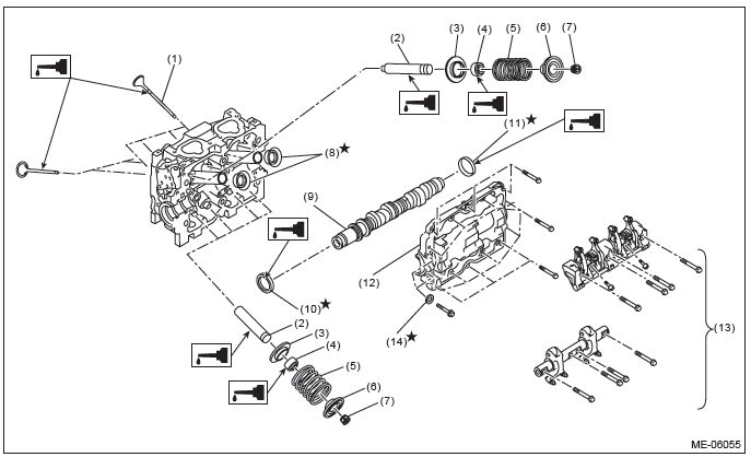
- Valve
- Valve guide
- Valve spring seat
- Oil seal
- Valve spring
- Valve spring retainer
- Valve spring retainer key
- Spark plug pipe gasket
- Camshaft
- Oil seal
- Plug
- Camshaft cap
- Seal washer
1) Install the valve spring and valve.
- Coat the stem of each valve with engine oil and insert the valve into valve guide.
NOTE: When inserting the valve into valve guide, use special care not to damage the oil seal lip.
- Set the cylinder head on ST.
ST 498267800 CYLINDER HEAD TABLE
- Install the valve spring and valve spring retainer.
NOTE: Be sure to install the valve spring with its close-coiled end facing the cylinder head side.
- Set the ST on valve spring.
ST 499718000 VALVE SPRING REMOVER
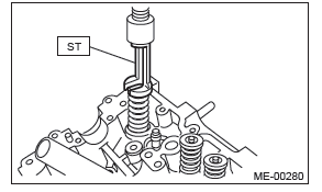
- Compress the valve spring and fit the valve spring retainer key.
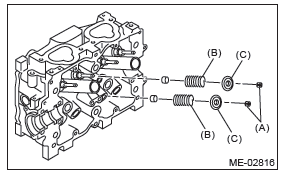
- Valve spring retainer key
- Valve spring
- Valve spring retainer
- After installing, tap the valve spring retainers lightly with a plastic hammer for better seating.
E: INSPECTION
1. CYLINDER HEAD
1) Check for cracks or damage. Use liquid penetrant tester on the important sections to check for fissures.
Check that there are no marks of gas leaking or water leaking on gasket installing surface.
2) Place the cylinder head on the ST.
ST 498267800 CYLINDER HEAD TABLE
3) Measure the warping of the cylinder head surface that mates with cylinder block using a straight edge (A) and thickness gauge (B).
If the warping exceeds the limit, correct the surface by grinding it with a surface grinder.
Warping limit:
0.035 mm (0.0014 in)
Grinding limit:
0.1 mm (0.004 in)
Standard height of cylinder head:
97.5 mm (3.84 in)
NOTE: Uneven torque for the cylinder head bolts can cause warpage. When reassembling, pay special attention to the torque so as to tighten evenly.
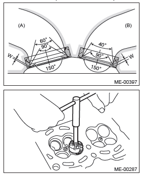
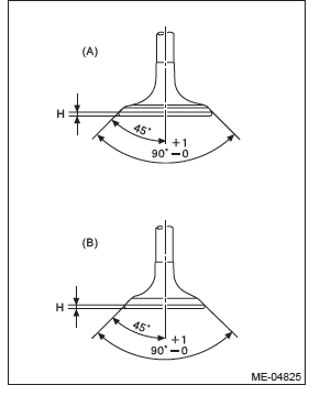
2. VALVE SEAT
Inspect the intake and exhaust valve seats, and correct the contact surfaces with a valve seat cutter if they are defective or when valve guides are replaced.
Contacting width of valve and valve seat W:
Standard
Intake (A)
0.8 - 1.4 mm (0.03 - 0.055 in)
Exhaust (B)
1.2 - 1.8 mm (0.047 - 0.071 in)
3. VALVE GUIDE
1) Check the clearance between valve guide and valve stem. The clearance can be checked by measuring respectively the outer diameter of valve stem with a micrometer and the inner diameter of valve guide with a caliper gauge.
Clearance between the valve guide and valve
stem:
Standard
Intake
0.035 - 0.062 mm (0.0014 - 0.0024 in)
Exhaust
0.040 - 0.067 mm (0.0016 - 0.0026 in)
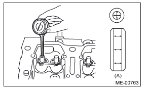
- Valve guide
2) If the clearance between the valve guide and valve stem exceeds the standard, replace the valve guide or valve itself, whichever shows greater amount of wear or damage. See the following procedure for valve guide replacement.
Valve guide inner diameter:
6.000 - 6.012 mm (0.2362 - 0.2367 in)
Valve stem outer diameters:
Intake
5.950 - 5.965 mm (0.2343 - 0.2348 in)
Exhaust
5.945 - 5.960 mm (0.2341 - 0.2346 in)
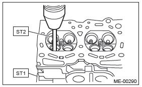
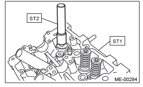
- Place the cylinder head on ST1 with the combustion chamber upward so that valve guides fit the holes in ST1.
- Insert the ST2 into valve guide and press it down to remove the valve guide.
ST1 498267800 CYLINDER HEAD TABLE
ST2 499767200 VALVE GUIDE REMOVER
- Turn the cylinder head upside down and place the ST as shown in the figure.
Intake side
ST 499767700 VALVE GUIDE ADJUSTER
Exhaust side
ST 499767800 VALVE GUIDE ADJUSTER
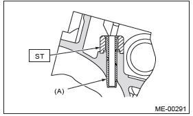
- Valve guide
- Before installing a new valve guide, make sure that neither scratches nor damages exist on the inner surface of valve guide holes in cylinder head.
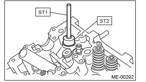
- Put a new valve guide, coated with sufficient oil, in the cylinder head, and insert the ST1 into valve guide. Press in until the valve guide upper end is flush with the upper surface of ST2.
ST1 499767200 VALVE GUIDE REMOVER
Intake side
ST2 499767700 VALVE GUIDE ADJUSTER
Exhaust side
ST2 499767800 VALVE GUIDE ADJUSTER
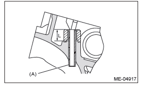
- Check the valve guide protrusion amount "L".
Valve guide protrusion amount L:
Intake
20.3 - 20.7 mm (0.799 - 0.815 in)
Exhaust
16.8 - 17.2 mm (0.661 - 0.677 in)
- Valve guide
- Ream the inside of valve guide using ST.
Put the ST in valve guide, and rotate the ST slowly clockwise while pushing it lightly. Bring the ST back while rotating it clockwise.
NOTE:
- Apply engine oil to the ST when reaming.
- If the inner surface of valve guide is damaged, the edge of ST should be slightly ground with oil stone.
- If the inner surface of valve guide becomes lustrous and the ST does not chip, use a new ST or remedy the ST.
ST 499767400 VALVE GUIDE REAMER
- After reaming, clean the valve guide to remove chips.
- Recheck the contact condition between valve and valve seat after replacing the valve guide.
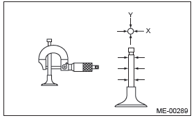
4. INTAKE AND EXHAUST VALVE
1) Inspect the flange of valve and valve stem, and replace the valve with a new part if damaged, worn, deformed, or if dimension "H" in the figure is outside of the specified limit.
Head edge thickness H:
Intake (A)
Standard
0.8 - 1.2 mm (0.03 - 0.047 in)
Exhaust (B)
Standard
1.0 - 1.4 mm (0.039 - 0.055 in)
2) Put a small amount of grinding compound on the valve seat surface, and lap the valve and valve seat surface. Replace with a new valve oil seal after lapping.
NOTE: It is possible to differentiate between the intake valve and the exhaust valve by their overall length.
Valve overall length:
Intake
120.6 mm (4.75 in)
Exhaust
121.7 mm (4.79 in)
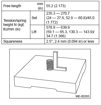
5. VALVE SPRING
1) Check the valve springs for damage, free length, and tension. Replace the valve spring if it is not within the standard value presented in the table.
2) To measure the squareness of the valve spring, stand the valve spring on a surface plate and measure its deflection at the top of the valve spring using a try square.
6. INTAKE AND EXHAUST VALVE OIL SEAL
1) For the following, replace the oil seal with a new part.
See the procedure 2) and subsequent for replacement procedures.
- When the lip is damaged.
- When the spring is out of the specified position.
- When readjusting the surfaces of valve and valve seat.
- When replacing the valve guide.
2) Place the cylinder head on ST1, and use ST2 to press-fit the oil seal.
ST1 498267800 CYLINDER HEAD TABLE
ST2 498857100 VALVE OIL SEAL GUIDE
NOTE:
- Apply engine oil to oil seal before press-fitting.
- When press-fitting the oil seal, do not use a hammer to strike in.
- The intake valve oil seals and exhaust valve oil seals are distinguished by their colors.
Color of rubber part:
Intake [Gray]
Exhaust [Green]
READ NEXT:
 Cylinder Block
A: REMOVAL
NOTE:
Before conducting this procedure, drain the engine
oil completely.
1) Remove the engine from the vehicle. <Ref. to
ME(H4SO)-31, REMOVAL, Engine Assembly.>
2) Remove the intake
Oil Switching Solenoid Valve
A: REMOVAL
1. RH SIDE
1) Disconnect the ground cable from battery.
2) Remove the cover (A) and clip (B) from air intake
boot assembly.
3) Loosen the clamp (A) which connects the air intake
boot asse
Exhaust
General Description
A: COMPONENT
Models other than C6 model
C6 model
Gasket
Spring
Chamber
Rear exhaust pipe
Cushion rubber (without protrusion)
Self-locking nut
Gasket
Muffler
Bolt
SEE MORE:
To increase the speed (by the “RES/ SET” switch)
Press the “RES/SET” switch to the “RES” side and hold it until the vehicle reaches
the desired speed. Then, release the switch. The vehicle speed at that moment will
be memorized and treated as the new set speed.
U.S.-spec. models
When the difference between the actual vehicle speed
Convex mirror (passenger side)
WARNING
Objects look smaller in a convex mirror and farther away than when viewed in
a flat mirror. Do not use the convex mirror to judge the distance of vehicles behind
you when changing lanes. Use the inside mirror (or glance backwards) to determine
the actual size and distance of objects t
