Subaru Outback (BR): Cylinder Block
A: REMOVAL
NOTE: Before conducting this procedure, drain the engine oil completely.
1) Remove the engine from the vehicle. <Ref. to ME(H4SO)-31, REMOVAL, Engine Assembly.>
2) Remove the intake manifold. <Ref. to FU(H4SO)-17, REMOVAL, Intake Manifold.>
3) Remove the crank pulley. <Ref. to ME(H4SO)- 45, REMOVAL, Crank Pulley.>
4) Remove the timing belt cover. <Ref. to ME(H4SO)-47, REMOVAL, Timing Belt Cover.>
5) Remove the timing belt. <Ref. to ME(H4SO)-48, REMOVAL, Timing Belt.>
6) Remove the crank sprocket. <Ref. to ME(H4SO)-54, REMOVAL, Crank Sprocket.>
7) Remove the generator and A/C compressor with their brackets.
8) Remove the cylinder head. <Ref. to ME(H4SO)- 63, REMOVAL, Cylinder Head.>
9) Remove the drive plate. (CVT model) <Ref. to CVT-133, REMOVAL, Drive Plate.>
10) Remove the clutch disc and cover. (MT model) <Ref. to CL-11, REMOVAL, Clutch Disc and Cover.>
11) Remove the flywheel. (MT model) <Ref. to CL- 14, REMOVAL, Flywheel.>
12) Remove the oil separator cover.
13) Remove the water by-pass pipe for heater.
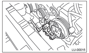
14) Remove the water pump. <Ref. to CO(H4SO)- 16, REMOVAL, Water Pump.>
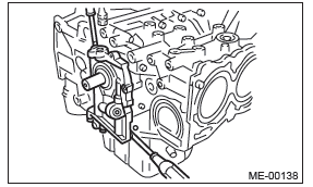
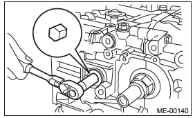
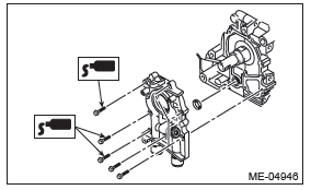
15) Remove the bolts which secure oil pump to cylinder block.
NOTE: When disassembling and checking the oil pump, loosen the relief valve plug before removing the oil pump.
16) Remove the oil pump from cylinder block using a flat tip screwdriver.
CAUTION: Be careful not to scratch the mating surface of cylinder block and oil pump.
17) Remove the front oil seal from the oil pump.
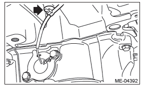
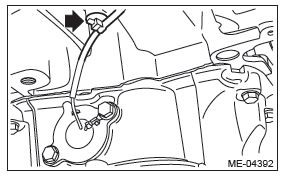
18) Remove the clip holding the oil level switch harness from cylinder block.
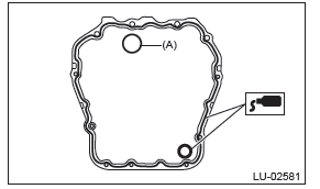
19) Remove the oil pan and cylinder block lower.
- Set the part so that the cylinder block LH is on the upper side.
- Remove the bolts which secure the oil pan to the cylinder block lower.
- Insert an oil pan cutter blade into the gap between cylinder block lower and oil pan, and remove the oil pan.
CAUTION: Do not use a screwdriver or similar tools in place of oil pan cutter.
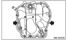
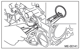
- Remove the bolts which secure the cylinder block lower to the cylinder block, and remove the cylinder block lower by using flat tip screwdriver.
CAUTION: Insert the flat tip screwdriver to the position shown in the figure, and be careful not to damage the mating surface of the cylinder block and cylinder block lower.
20) Remove the oil strainer.
21) Remove the baffle plate.
22) Remove the oil filter. <Ref. to LU(H4SO)-36, REMOVAL, Engine Oil Filter.>
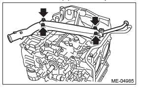
23) Remove the water pipe assembly.
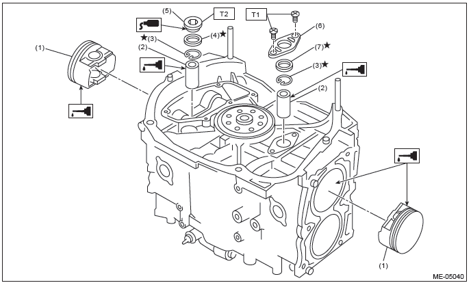
- Service hole plug
- Gasket
- Snap ring
- Piston pin
- Service hole cover
- O-ring
- Seal washer
- Washer
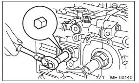
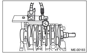
24) Remove the service hole plugs using a hexagon wrench [14 mm].
25) Remove the service hole cover.
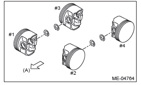
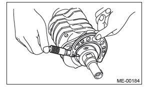
26) Rotate the crankshaft to bring #1 and #2 pistons to bottom dead center position, then remove the piston snap ring through service hole of #1 and #2 cylinders.
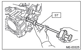
27) Draw out the piston pin from #1 and #2 pistons using ST.
ST 499097700 PISTON PIN REMOVER ASSY
NOTE: Be careful not to confuse the original combination of piston, piston pin and cylinder.
28) Similarly draw out the piston pins from #3 and #4 pistons.
29) Remove the cylinder block connecting bolt on the RH side.
30) Loosen the cylinder block connecting bolt on the LH side by 2 to 3 turns.
31) Set the part so that the cylinder block LH is on the upper side, and remove the cylinder block connecting bolt.
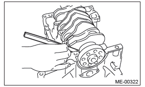
32) Separate the cylinder block LH and RH.
NOTE: When separating the cylinder block, do not allow the connecting rod to fall or damage the cylinder block.
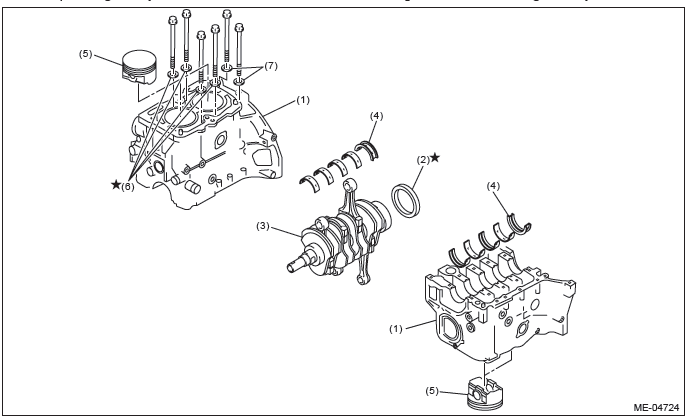
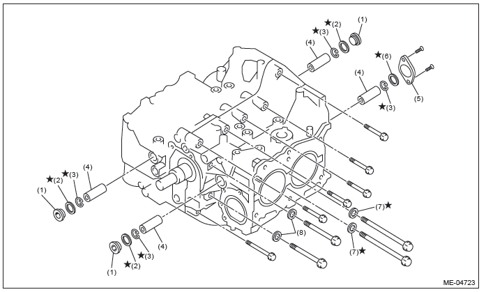
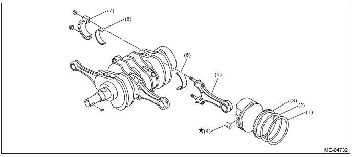
- Cylinder block
- Rear oil seal
- Crankshaft
- Crankshaft bearing
- Piston
- Seal washer
- Washer
33) Remove the rear oil seal.
34) Remove the crankshaft along with the connecting rods.
35) Remove the crankshaft bearings from cylinder block using a hammer handle.
NOTE:
- Press the crankshaft bearing at the end opposite to locking lip to remove.
- Be careful not to confuse the crankshaft bearing combination.
36) Remove each piston from the cylinder block using a wooden bar or hammer handle.
NOTE: Be careful not to confuse the original combination of piston and cylinder.
B: INSTALLATION
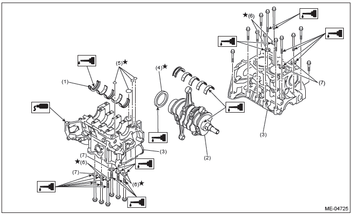
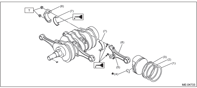
- Crankshaft bearing
- Crankshaft
- Cylinder block
- Rear oil seal
- O-ring
- Seal washer
- Washer
1) Remove oil on the mating surface of cylinder block before installation. Apply a coat of engine oil to the bearing and crankshaft journal.
2) Position the crankshaft and O-ring on cylinder block RH.
NOTE: Use new O-rings.
3) Apply liquid gasket to the mating surfaces of cylinder block RH, and position cylinder block LH.
NOTE:
- Install within 5 min. after applying liquid gasket.
- Do not allow liquid gasket to jut into O-ring grooves, oil passages, bearing grooves, etc.
Liquid gasket: THREE BOND 1217G (Part No. K0877Y0100) or equivalent
4) Apply a coat of engine oil to the washer and bolt thread.
NOTE: Use a new seal washer.
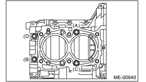
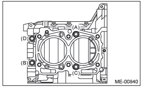
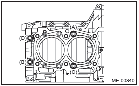
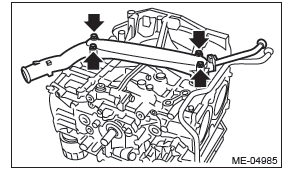
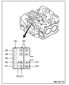
5) Tighten the 10 mm cylinder block connecting bolts on the LH side (A - D) in alphabetical order.
Tightening torque: 10 N*m (1.0 kgf-m, 7.4 ft-lb)
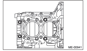
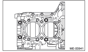
6) Tighten the 10 mm cylinder block connecting bolts on the RH side (E - J) in alphabetical order.
Tightening torque: 10 N*m (1.0 kgf-m, 7.4 ft-lb)
7) Tighten the LH side cylinder block connecting bolts (A - D) further in alphabetical order.
Tightening torque: 18 N*m (1.8 kgf-m, 13.3 ft-lb)
8) Tighten the RH side cylinder block connecting bolts (E - J) further in alphabetical order.
Tightening torque: 18 N*m (1.8 kgf-m, 13.3 ft-lb)
9) Tighten the LH side cylinder block connecting bolts (A - D) further in alphabetical order.
- (A), (C): Angle tightening
Tightening angle: 90º
- (B), (D): Torque tightening
Tightening torque: 40 N*m (4.1 kgf-m, 29.5 ft-lb)
10) Tighten the RH side cylinder block connecting bolts (E - J) further in alphabetical order.
Tightening angle: 90º
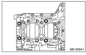
11) Tighten the 8 mm and 6 mm cylinder block connecting bolts on the LH side (A - H) in alphabetical order.
Tightening torque:
(A) - (G): 25 N*m (2.5 kgf-m, 18.4 ft-lb)
(H): 6.4 N*m (0.7 kgf-m, 4.7 ft-lb)
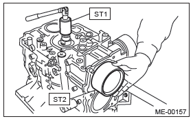
12) Apply a coat of engine oil to the oil seal inner periphery and outer periphery, and install the rear oil seal using ST1 and ST2.
NOTE: Use a new rear oil seal.
ST1 499597100 CRANKSHAFT OIL SEAL
GUIDE
ST2 499587200 CRANKSHAFT OIL SEAL INSTALLER
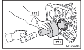
- Rear oil seal
- Mounting bolts for drive plate or flywheel
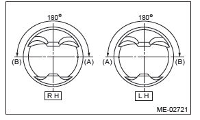
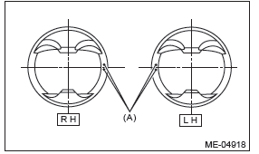
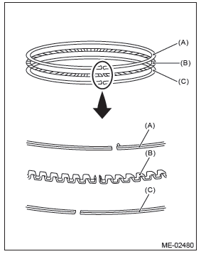
13) Position the top ring gap at (A) or (B) in the figure.
14) Position the second ring gap at 180º on the reverse side the top ring gap.
15) Position the upper rail gap at (C) in the figure.
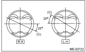
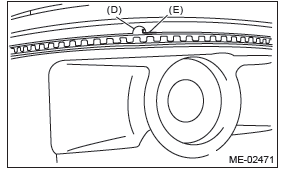
16) Align the upper rail spin stopper (E) to the side hole (D) on the piston.
17) Position the expander gap at (F) in the figure on the 180º opposite direction of (C).
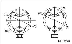
18) Set the lower rail gap at position (G), located 120º clockwise from (C) in the figure.
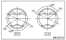
NOTE:
- Make sure ring gaps do not face the same direction.
- Make sure ring gaps are not within the piston skirt area.
19) Install the snap ring.
Before positioning the piston on the cylinder block, attach the snap ring in the service hole of the cylinder block, and the piston hole on the opposite side.
NOTE: Use new snap rings.
- Front side
- Piston
- Piston pin
- Snap ring
- Gasket
- Service hole plug
Tightening torque: N*m (kgf-m, ft-lb)
T: 70 (7.1, 51.6)
20) Install the piston.
- Set the parts so that the #1 and #2 cylinders are on the upper side.
- Using the ST1, turn the crankshaft so that #1 and #2 connecting rods are set at bottom dead center.
ST1 499987500 CRANKSHAFT SOCKET
- Apply a coat of engine oil to the pistons and cylinders and insert pistons in their cylinders using ST2.
ST2 498747300 PISTON GUIDE
NOTE: Face the piston front mark towards the front of the engine.
- Front mark
21) Install the piston pin.
- Apply a coat of engine oil to ST3.
- Insert ST3 into the service hole to align piston pin hole with connecting rod small end.
ST3 499017100 PISTON PIN GUIDE
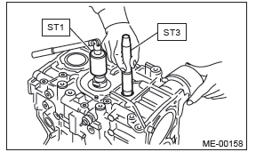
- Apply a thin coat of engine oil to piston pin, and insert the piston pin into piston and connecting rod through service hole.
- Install the snap ring.
NOTE: Use new snap rings.
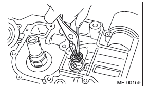
- Apply liquid gasket to the threaded portion of the service hole plug.
Liquid gasket: THREE BOND 1105 (Part No. 004403010) or equivalent
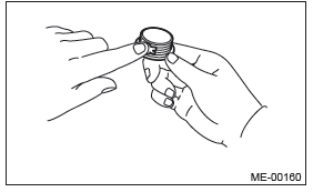
- Install the service hole plug and gasket.
NOTE: Use a new gasket.
Tightening torque: 70 N*m (7.1 kgf-m, 51.6 ft-lb)
- Piston
- Piston pin
- Snap ring
- Gasket
- Service hole plug
- Service hole cover
- O-ring
Tightening torque: N*m (kgf-m, ft-lb)
T1: 6.4 (0.7, 4.7)
T2: 70 (7.1, 51.6)
- Set the parts so that the #3 and #4 cylinders are on the upper side. Following the same procedures as used for #1 and #2 cylinders, install the pistons and piston pins.
- Install the service hole cover.
NOTE: Use new O-rings.
Tightening torque: 6.4 N*m (0.7 kgf-m, 4.7 ft-lb)
22) Install the water pipe assembly.
NOTE: Use new O-rings.
Tightening torque: 6.4 N*m (0.7 kgf-m, 4.7 ft-lb)
23) Install the baffle plate.
NOTE:
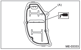
- Use a new seal.
- Make sure that the seals (A) are installed securely on the baffle plate in a direction as shown in the figure below.
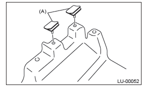
Tightening torque: 6.4 N*m (0.7 kgf-m, 4.7 ft-lb)
24) Apply liquid gasket to the mating surfaces of cylinder block lower, and install the cylinder block lower.
CAUTION: Be careful not to apply any liquid gasket to the O-ring attachment section.
NOTE:
- Use new O-rings.
- Before installing the cylinder block lower, clean the mating surface of cylinder block lower and cylinder block.
- Install within 5 min. after applying liquid gasket.
Liquid gasket: THREE BOND 1217G (Part No. K0877Y0100) or equivalent
- O-ring
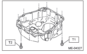
Tightening torque:
T1: 6.4 N*m (0.7 kgf-m, 4.7 ft-lb)
T2: 16 N*m (1.6 kgf-m, 11.8 ft-lb)
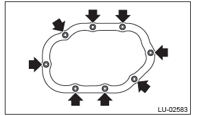
25) Apply liquid gasket to the mating surfaces of oil pan, and install the oil pan.
NOTE:
- Before installing the oil pan, clean the mating surface of oil pan and cylinder block.
- Install within 5 min. after applying liquid gasket.
Liquid gasket: THREE BOND 1217G (Part No. K0877Y0100) or equivalent
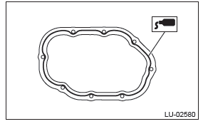
Tightening torque: 5 N*m (0.5 kgf-m, 3.7 ft-lb)
26) Secure the oil level switch harness to the cylinder block with clip.
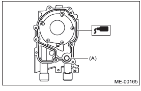
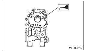
27) Apply liquid gasket to the mating surfaces of the oil separator cover and the threaded portion of bolt (A) shown in the figure (when reusing the bolt), and then install the oil separator cover.
NOTE:
- Install within 5 min. after applying liquid gasket.
- Use new oil separator cover.
Liquid gasket:
- Mating surface THREE BOND 1217G (Part No. K0877Y0100) or equivalent
- (A) bolt thread (when reusing bolts) THREE BOND 1324 (Part No. 004403042) or equivalent
Tightening torque: 6.4 N*m (0.7 kgf-m, 4.7 ft-lb)
28) Install the drive plate. (CVT model) <Ref. to CVT-133, INSTALLATION, Drive Plate.>
29) Install the flywheel. (MT model) <Ref. to CL-14, INSTALLATION, Flywheel.>
30) Install the clutch disc and cover. (MT model) <Ref. to CL-11, INSTALLATION, Clutch Disc and Cover.>
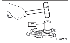
31) Install the oil pump.
- Using the ST, install the front oil seal.
ST 499587100 OIL SEAL INSTALLER
NOTE: Use a new front oil seal.
- Apply liquid gasket to the mating surfaces of oil pump.
NOTE: Install within 5 min. after applying liquid gasket.
Liquid gasket: THREE BOND 1217G (Part No. K0877Y0100) or equivalent
- O-ring
- Apply a thin coat of engine oil to the inside of front oil seal.
- Install the oil pump to cylinder block.
CAUTION:
- Be careful not to damage the front oil seal during installation.
- Make sure the front oil seal lip is not folded.
NOTE:
- Align the flat surface of oil pump's inner rotor with that of crankshaft before installation.
- Use new O-rings.
- Do not forget to assemble O-rings.
- Apply liquid gasket to the three bolts thread shown in figure. (when reusing bolts)
Liquid gasket: THREE BOND 1324 (Part No. 004403042) or equivalent
Tightening torque: 6.4 N*m (0.7 kgf-m, 4.7 ft-lb)
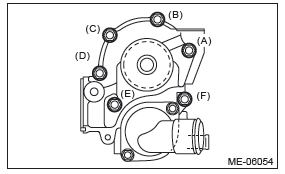
32) Install the water pump and gasket.
NOTE:
- When installing the water pump, tighten bolts in two stages in alphabetical order as shown in the figure.
- Use a new gasket.
Tightening torque:
First: 12 N*m (1.2 kgf-m, 8.9 ft-lb)
Second: 12 N*m (1.2 kgf-m, 8.9 ft-lb)
33) Install the water by-pass pipe for heater.
Tightening torque: 6.4 N*m (0.7 kgf-m, 4.7 ft-lb)
34) Install the oil filter. <Ref. to LU(H4SO)-36, INSTALLATION, Engine Oil Filter.>
35) Install the cylinder head. <Ref. to ME(H4SO)- 63, INSTALLATION, Cylinder Head.>
36) Install the generator and A/C compressor with their brackets.
Tightening torque: 36 N*m (3.7 kgf-m, 26.6 ft-lb)
37) Install the crank sprocket. <Ref. to ME(H4SO)- 54, INSTALLATION, Crank Sprocket.>
38) Install the timing belt. <Ref. to ME(H4SO)-49, INSTALLATION, Timing Belt.>
39) Adjust the valve clearance. <Ref. to ME(H4SO)-30, ADJUSTMENT, Valve Clearance.>
40) Install the rocker cover.
- Install the rocker cover gasket to the rocker cover.
NOTE: Use a new rocker cover gasket.
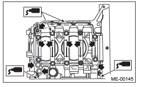
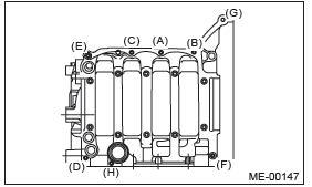
- Temporarily tighten the rocker cover bolts in alphabetical order shown in the figure, and then tighten to specified torque in alphabetical order in two steps.
Tightening torque:
First
6.4 N*m (0.7 kgf-m, 4.7 ft-lb)
Second (only (a) and (b) are tightened)
6.4 N*m (0.7 kgf-m, 4.7 ft-lb)
- RH side
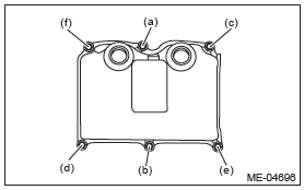
- LH side
41) Install the timing belt cover. <Ref. to ME(H4SO)-47, INSTALLATION, Timing Belt Cover.>
42) Install the crank pulley. <Ref. to ME(H4SO)-45, INSTALLATION, Crank Pulley.>
43) Install the intake manifold. <Ref. to FU(H4SO)- 21, INSTALLATION, Intake Manifold.>
44) Install the engine to the vehicle. <Ref. to ME(H4SO)-35, INSTALLATION, Engine Assembly.>
C: DISASSEMBLY
- Top ring
- Second ring
- Oil ring
- Snap ring
- Connecting rod
- Connecting rod bearing
- Connecting rod cap
1) Remove the connecting rod cap.
2) Remove the connecting rod bearing.
NOTE: Keep the removed connecting rods, connecting rod caps and bearings in order so that they are kept in their original combinations/groups, and not mixed together.
3) Remove the piston rings using piston ring expander.
4) Remove the oil ring by hand.
NOTE: Arrange the removed piston rings in proper order, to prevent confusion.
5) Remove the snap ring.
D: ASSEMBLY
- Top ring
- Second ring
- Oil ring
- Snap ring
- Side mark
- Connecting rod
- Connecting rod bearing
- Connecting rod cap
Tightening torque: N*m (kgf-m, ft-lb)
T: 45 (4.6, 33.2)
1) Apply engine oil to the surface of the connecting rod bearings, and install the connecting rod bearings on connecting rods and connecting rod caps.
2) Position each connecting rod with the side with a side mark facing forward, and install it.
3) Attach the connecting rod cap, and tighten with connecting rod nut.
Make sure the arrow on connecting rod cap faces the front during installation.
NOTE:
- Each connecting rod has its own mating cap.
Make sure that they are assembled correctly by checking their matching number.
- When tightening the connecting rod nuts, apply oil on the threads.
Tightening torque: 45 N*m (4.6 kgf-m, 33.2 ft-lb)
4) Install the oil ring upper rail, expander and lower rail by hand.
5) Install the second ring and top ring using piston ring expander.
NOTE: Assemble so that the piston ring mark "R" faces the top side of the piston.
E: INSPECTION
1. CYLINDER BLOCK
1) Check for cracks or damage. Use liquid penetrant tester on the important sections to check for fissures. Check that there are no marks of gas leaking or water leaking on gasket installing surface.
2) Check the oil passages for clogging.
3) Inspect the cylinder head surface that mates with cylinder block for warping by using a straight edge, and correct by grinding if necessary.
Warping limit:
0.025 mm (0.00098 in)
Grinding limit:
0.1 mm (0.004 in)
Standard height of cylinder block:
201.0 mm (7.91 in)
2. CYLINDER AND PISTON
1) The cylinder bore size is stamped on the front upper face of the cylinder block.
NOTE:
- Measurement should be performed at a temperature of 20ºC (68ºF).
- Standard sized pistons are classified into two grades, "A" and "B". These grades should be used as guide lines in selecting a standard piston.
Standard diameter:
A: 99.505 - 99.515 mm (3.9175 - 3.9179 in)
B: 99.495 - 99.505 mm (3.9171 - 3.9175 in)
- Main journal size mark
- Cylinder block (RH) - (LH) combination mark
- #1 cylinder bore size mark
- #2 cylinder bore size mark
- #3 cylinder bore size mark
- #4 cylinder bore size mark
2) Measure inner diameter of each cylinder.
Measure the inner diameter of each cylinder in both the thrust and piston pin directions at the heights as shown in the figure, using a cylinder bore gauge.
NOTE: Measurement should be performed at a temperature of 20ºC (68ºF).
Cylindricality:
Limit
0.015 mm (0.0006 in)
Out-of-roundness:
Limit
0.010 mm (0.0004 in)
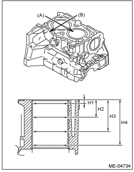
- Piston pin direction
- Thrust direction
- H1 10 mm (0.39 in)
- H2 45 mm (1.77 in)
- H3 80 mm (3.15 in)
- H4 115 mm (4.53 in)
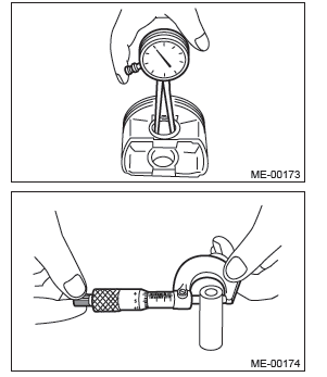
3) When the piston is to be replaced due to general or cylinder wear, select a suitable sized piston by measuring the piston clearance.
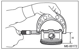
4) Measure outer diameter of each piston.
Measure the outer diameter of each piston at the height as shown in the figure. (Thrust direction) NOTE: Measurement should be performed at a temperature of 20ºC (68ºF).
Piston grade point H:
38.2 mm (1.504 in)
Piston outer diameter:
Standard
A: 99.510 - 99.520 mm (3.9177 - 3.9181 in)
B: 99.500 - 99.510 mm (3.9173 - 3.9177 in)
0.25 mm (0.0098 in) oversize:
99.750 - 99.770 mm (3.9272 - 3.9280 in)
0.50 mm (0.0197 in) oversize:
100,000 - 100.020 mm (3.9370 - 3.9378 in)
5) Calculate the clearance between cylinder and piston.
NOTE: Measurement should be performed at a temperature of 20ºC (68ºF).
Clearance between cylinder and piston at 20ºC
(68ºF):
Standard
-0.015 - 0.005 mm (-0.00059 - 0.00020 in)
6) Boring and honing
- If any of the measured value of cylindricality, out-of-roundness or cylinder-to-piston clearance is out of standard or if there is any damage on the cylinder wall, rebore it to replace with an oversize piston.
CAUTION: When any of the cylinders needs reboring, all other cylinders must be bored at the same time, and replaced with oversize pistons.
- If the cylinder inner diameter exceeds the limit after boring and honing, replace the cylinder block.
NOTE: Immediately after reboring, the cylinder diameter may differ from its real diameter due to temperature rise. Thus, when measuring the cylinder diameter, wait until it has cooled to room temperature.
Cylinder inner diameter boring limit: To 100.005 mm (3.9372 in)
3. PISTON AND PISTON PIN
1) Check the piston and piston pin for damage, cracks or wear. Replace if faulty.
2) Check the piston ring groove for wear or damage.
Replace if faulty.
3) Make sure that the piston pin can be inserted into the piston pin hole with a thumb at 20ºC (68ºF).
Replace if faulty.
Clearance between piston pin hole and piston
pin:
Standard
0.004 - 0.008 mm (0.0002 - 0.0003 in)
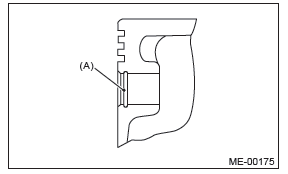
4) Check the snap ring installation groove (A) on the piston for burr. If necessary, remove burr from the groove so that the piston pin can lightly move.
5) Check the snap ring for distortion, cracks and wear.
4. PISTON RING
1) If the piston ring is broken, damaged or worn, or if its tension is insufficient, or when the piston is replaced, replace the piston ring with a new part of the same size as piston.
NOTE:
- The top ring and second ring have the mark to determine the direction for installing. When installing the ring to piston, face marks to the top side.
- Oil ring consists of the upper rail, expander and lower rail. When installing oil ring on piston, be careful of the direction of each rail.
- Upper rail
- Expander
- Lower rail
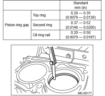
2) Using the piston, insert the piston ring and oil ring into the cylinder block so that they are perpendicular to the cylinder wall, and measure the piston ring gap using a thickness gauge.
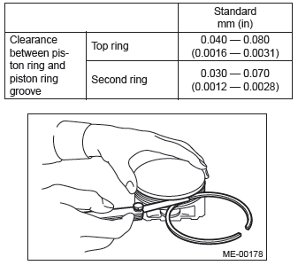
3) Fit the piston ring straight into the piston ring groove, then measure the clearance between piston ring and piston ring groove with a thickness gauge.
NOTE: Before measuring the clearance, clean the piston ring groove and piston ring.
5. CONNECTING ROD
1) Replace the connecting rod, if the large or small end thrust surface is damaged.
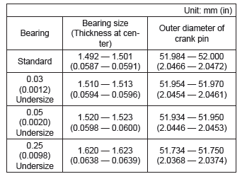
2) Check for bend or twist using a connecting rod aligner. Replace the connecting rod if the bend or twist exceeds the limit.
Limit of bend or twist per 100 mm (3.94 in) in length: 0.10 mm (0.0039 in)
- Thickness gauge
- Connecting rod
3) Install the connecting rod with bearings attached to the crankshaft, and using a thickness gauge, measure the thrust clearance. If the thrust clearance exceeds the standard or uneven wear is found, replace the connecting rod.
Connecting rod thrust clearance: Standard 0.070 - 0.330 mm (0.0028 - 0.0130 in)
4) Inspect the connecting rod bearing for scar, peeling, seizure, melting, wear, etc.
5) Measure the oil clearance on each connecting rod bearing using plastigauge. If any oil clearance is not within the standard, replace the defective bearing with a new part of standard size or undersize as necessary.
Connecting rod oil clearance: Standard 0.016 - 0.044 mm (0.0006 - 0.0017 in)
6) Inspect the bushing at connecting rod small end, and replace with a new part if worn or damaged.
7) Measure the piston pin clearance at connecting rod small end. If the measured value is not within the standard, replace it with a new part.
Clearance between piston pin and bushing: Standard 0 - 0.022 mm (0 - 0.0009 in)
8) The replacement procedure for the connecting rod small end bushing is as follows.
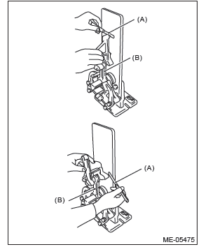
- Remove the bushing from connecting rod with ST and press.
- Press the bushing with the ST after applying oil on the periphery of new bushing.
ST 499037100 CONNECTING ROD BUSHING REMOVER AND INSTALLER
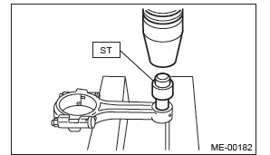
- Make two 3 mm (0.12 in) holes in the pressed bushing to match the pre-manufactured holes on the connecting rod, then ream the inside of the bushing.
- After completion of reaming, clean the bushing to remove chips.
6. CRANKSHAFT AND CRANKSHAFT BEARING
1) Clean the crankshaft completely, and check it for cracks using liquid penetrant tester. If defective, replace the crankshaft.
2) Measure warping of the crankshaft. If it exceeds the limit, correct or replace it.
NOTE: If a suitable V-block is not available, using just the #1 and #5 crankshaft bearings on cylinder block, position the crankshaft on cylinder block. Then, measure the crankshaft bend using a dial gauge.
Crankshaft bend limit: 0.035 mm (0.0014 in)
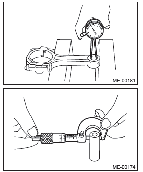
3) Inspect the crank journal and crank pin for wear. If they are not within the standard, replace the bearing with a suitable (undersize) one, and replace or grind to correct the crankshaft as necessary. When grinding the crank journal or crank pin, finish them to the specified dimensions according to the undersize bearing to be used.
Crank pin:
Cylindricality
Limit
0.004 mm (0.0002 in)
Out-of-roundness
Limit
0.003 mm (0.0001 in)
Grinding limit (dia.)
To 51.750 mm (2.0374 in)
Crank journal:
Cylindricality
Limit
0.006 mm (0.0002 in)
Out-of-roundness
Limit
0.005 mm (0.0002 in)
Grinding limit (dia.)
To 59.758 mm (2.3527 in)
4) Use a thickness gauge to measure the thrust clearance of crankshaft at #5 crank journal bearing.
If clearance exceeds the standard, replace the bearing.
Crankshaft thrust clearance: Standard 0.030 - 0.115 mm (0.0012 - 0.0045 in)
5) Inspect individual crankshaft bearings for signs of flaking, seizure, melting and wear.
6) Measure the oil clearance on each crankshaft bearing using plastigauge. If the measured value is out of standard, replace the defective bearing with an undersize one, and replace or grind to correct the crankshaft as necessary.
Crankshaft oil clearance: Standard 0.010 - 0.030 mm (0.0004 - 0.0012 in)
READ NEXT:
 Oil Switching Solenoid Valve
A: REMOVAL
1. RH SIDE
1) Disconnect the ground cable from battery.
2) Remove the cover (A) and clip (B) from air intake
boot assembly.
3) Loosen the clamp (A) which connects the air intake
boot asse
Exhaust
General Description
A: COMPONENT
Models other than C6 model
C6 model
Gasket
Spring
Chamber
Rear exhaust pipe
Cushion rubber (without protrusion)
Self-locking nut
Gasket
Muffler
Bolt
Cooling
General Description
A: SPECIFICATION
B: COMPONENT
1. WATER PUMP
Water pump ASSY
Gasket
Heater by-pass hose
Thermostat
Gasket
Thermostat cover
Clip
Tightening torque: N*m (kgf-m, ft-lb)
T1:
SEE MORE:
Starter
A: REMOVAL
1) Disconnect the ground cable from battery.
2) Remove the cover (A) and clip (B) from air intake
boot assembly. (2.5 L non-turbo model)
3) Loosen the clamp (A) which connects the air intake
boot assembly and air cleaner case. (2.5 L
non-turbo model)
4) Loosen the clamp (B) which connec
Main fuse
Main fuse box
The main fuses are designed to melt during an overload to prevent damage to the
wiring harness and electrical equipment. Check the main fuses if any electrical
component fails to operate (except the starter motor) and other fuses are good.
A melted main fuse must be replaced.
