Subaru Outback (BR): General Description of Exterior Body Panels
A: SPECIFICATION
Refer to Body Repair Manual for the dimensions of the body.
B: COMPONENT
1. FRONT HOOD
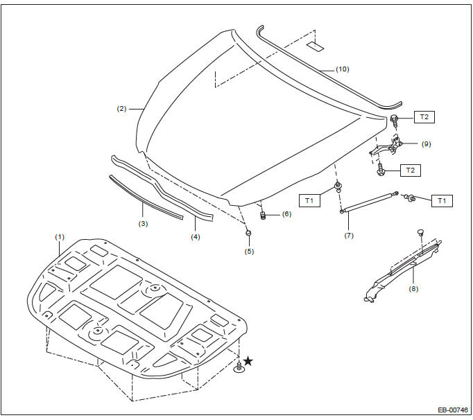
- Insulator
- Front hood panel ASSY
- Front grille seal ASSY
- Front hood seal ASSY
- Front hood stopper
- Buffer (hood side)
- Damper stay ASSY
- Fender cover ASSY UPR
- Hinge
- Cowl panel seal
Tightening torque: N*m (kgf-m, ft-lb)
T1: 20 (2.04, 14.8)
T2: 25 (2.55, 18.4)
2. FRONT FENDER
Tightening torque: N*m (kgf-m, ft-lb)
T: 7.5 (0.76, 5.5)
3. FRONT DOOR
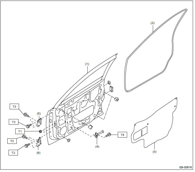
- Front door panel
- Front door weather strip
- Sealing cover
- Checker
- Upper hinge
- Lower hinge
Tightening torque: N*m (kgf-m, ft-lb)
T1: 7.5 (0.76, 5.5)
T2: 25 (2.55, 18.4)
T3: 30 (3.06, 22.1)
T4: 33 (3.36, 24.3)
4. REAR DOOR
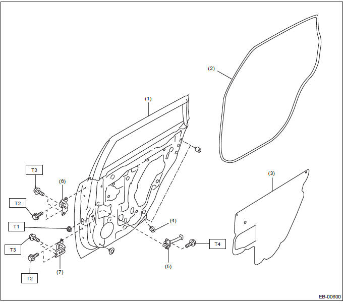
- Rear door panel
- Rear door weather strip
- Sealing cover
- Rear door catcher
- Checker
- Upper hinge
- Lower hinge
Tightening torque: N*m (kgf-m, ft-lb)
T1: 7.5 (0.76, 5.5)
T2: 25 (2.55, 18.4)
T3: 30 (3.06, 22.1)
T4: 33 (3.36, 24.3)
5. TRUNK LID PANEL
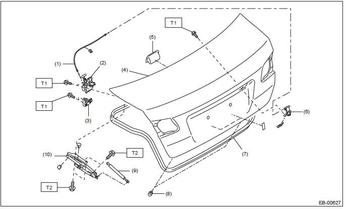
- Trunk release cable ASSY
- Trunk lid latch and actuator ASSY
- Striker
- Trunk lid panel ASSY
- Trunk lid inner handle
- Trunk lid key cylinder ASSY
- Weather strip
- Trunk lid stopper
- Trunk lid damper stay
- Trunk lid hinge ASSY
Tightening torque: N*m (kgf-m, ft-lb)
T1: 7.5 (0.76, 5.5)
T2: 25 (2.55, 18.4)
6. REAR GATE
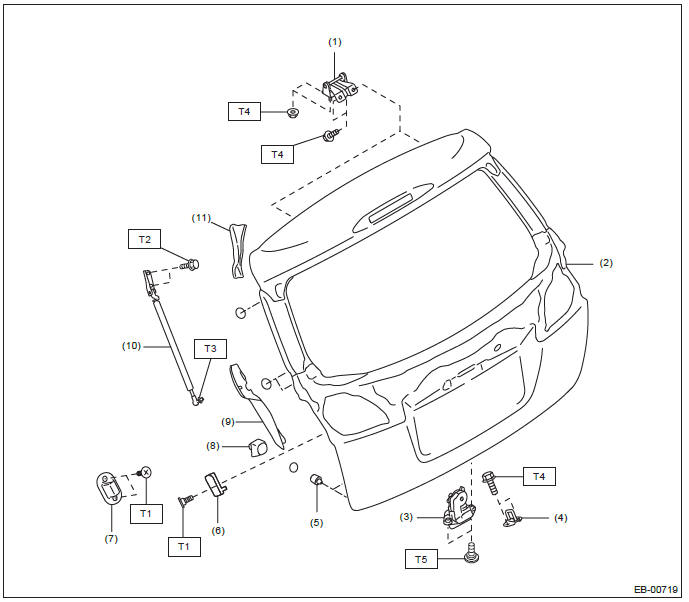
- Hinge
- Rear gate panel
- Rear gate latch and actuator ASSY
- Striker
- Stopper rubber
- Buffer (rear gate side)
- Buffer (body side)
- Rear gate spacer (mounted to the body)
- Rear gate cover
- Rear gate damper stay
- Rear gate drip rubber
Tightening torque: N*m (kgf-m, ft-lb)
T1: 7.5 (0.76, 5.5)
T2: 16 (1.63, 11.8)
T3: 20 (2.04, 14.8)
T4: 25 (2.55, 18.4)
T5: 28 (2.86, 20.7)
C: CAUTION
Exterior body panels are heavy. When removing and installing them, do not drop and damage the panels. Also, be careful not to scratch the coated surfaces of the panels.
D: PREPARATION TOOL
1. SPECIAL TOOL
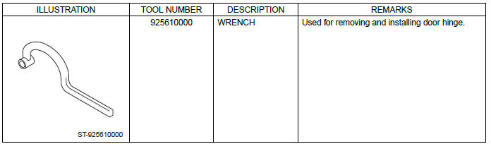
2. GENERAL TOOL

READ NEXT:
 Front Hood
A: REMOVAL
1. FRONT HOOD INSULATOR
Release the clips to remove the front hood insulator.
CAUTION:
Do not reuse any clips damaged during removal. The damaged clip cannot fix the
insulator securely.
T
Front Fender
A: REMOVAL
1) Disconnect the ground cable from battery.
2) Remove the bumper face assembly.
Remove the clips, turn over the front mud guard, and disconnect the fog
light connector. (Model with
f
Front Door
A: REMOVAL
1) Disconnect the ground cable from battery.
2) Remove the front door trim. <Ref. to EI-60, FRONT DOOR, REMOVAL, Door Trim.>
3) Remove the outer mirror assembly. <Ref. to GW-28,
SEE MORE:
Battery (inspection, removal, installation)
A: REMOVAL
1) After disconnecting the battery ground terminal, remove the terminal cover, then disconnect the positive terminal.
2) Remove the battery cable holder from the battery rod.
3) Remove flange nut from the battery rod and remove battery holder.
Remove the battery.
B: INSTALLATION
Child safety locks
WARNING
Always turn the child safety locks to the “LOCK” position when children sit on
the rear seat. Serious injury could result if a child accidentally opens the door
and falls out.
Each rear door has a child safety lock that prevents the door from being opened
even if the inside doo
