Subaru Outback (BR): Front Fender
A: REMOVAL
1) Disconnect the ground cable from battery.
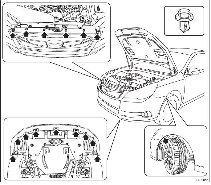
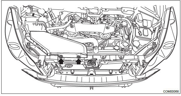
2) Remove the bumper face assembly.
- Remove the clips, turn over the front mud guard, and disconnect the fog light connector. (Model with fog light)
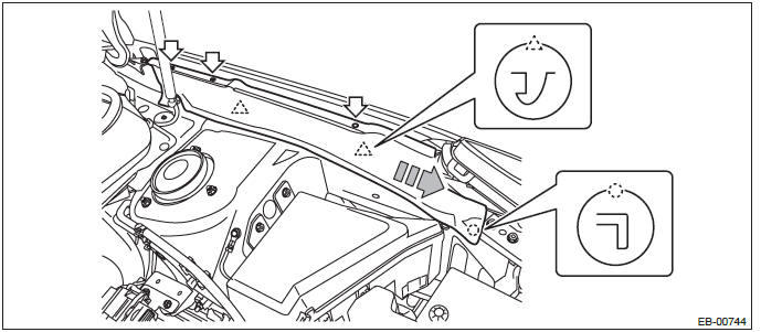
- Remove the clips at the upper side of the bumper.
- Remove the clips from the fender.
- Remove the clips at the lower side of bumper.
- Detach the flange section on the bumper face side from the bracket side front UPR.
CAUTION: Do not pull forcibly. It may damage the flange sections of the bumper face.
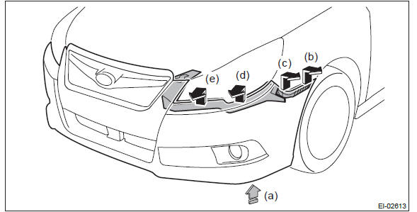
NOTE: Pushing up the lower side (a) of the fog light, remove from (b) to (e).
Detach the opposite side in the same manner.
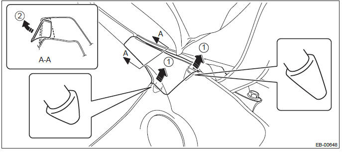
3) Remove the cowl panel side.
- Detach the pins of the cowl panel side.
- Remove the cowl panel side from inside the fender panel by pulling it.
CAUTION: Applying excessive pulling force may damage the cowl panel side. If it is difficult to remove, use a plastic remover or equivalent tool.
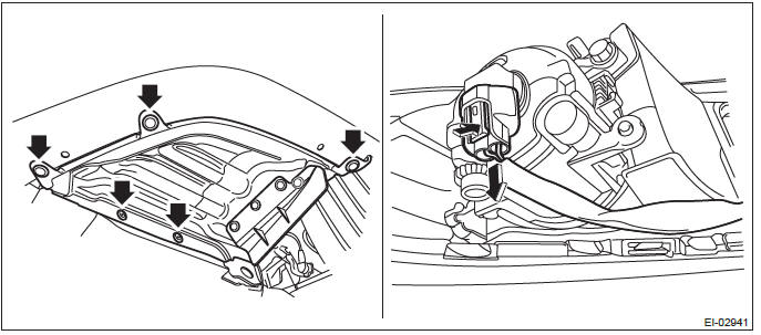
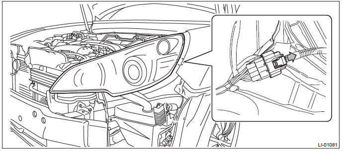
4) Remove the headlight assembly.
- Remove the fender cover assembly UPR.
- Remove the clip.
- Release the claws of the fender cover assembly UPR by pulling it forward and remove the fender cover.
- Remove the headlight assembly.
NOTE: When removing the RH headlight, remove the air intake duct.
- Remove the bolts and two clips, and pull out the headlight assembly to the front of the vehicle.
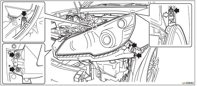
- Disconnect the connector and remove the headlight assembly.
- Headlight connector RH
- Headlight connector LH
5) Remove the clips, and then remove the side sill garnish.
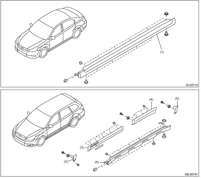
- Side sill garnish ASSY (sedan model)
- Garnish ASSY front fender (OUTBACK model)
- Garnish ASSY front door (OUTBACK model)
- Garnish ASSY rear door (OUTBACK model)
- Garnish ASSY rear quarter (OUTBACK model)
- Side sill garnish ASSY (OUTBACK model)
6) Remove the front fender panel.
- Remove the mud guard clips.
- Remove the bolt, and remove the front fender panel.
B: INSTALLATION
1) Install each part in the reverse order of removal.
CAUTION:
- After the installation of front fender panel, be sure to perform headlight beam adjustment. <Ref. to LI-27, HEADLIGHT BEAM ADJUSTMENT, ADJUSTMENT, Headlight Assembly.>
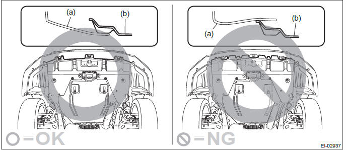
- Install the bumper face so that the under cover front end (b) comes inside the front bumper face (a).
Tightening torque:
Front fender panel: 7.5 N*m (0.76 kgf-m, 5.5 ft-lb)
Headlight assembly: 7.5 N*m (0.76 kgf-m, 5.5 ft-lb)
NOTE: Install while paying attention to make a uniform clearance around the front fender panel.
- Front fender panel - Front hood panel: <Ref. to EB-13, ADJUSTMENT, Front Hood.>
- Front fender panel - Front door panel: <Ref. to EB-28, ADJUSTMENT, Front Door.>
2) Adjust the fog light beam. (Model with fog light) <Ref. to LI-41, FOG LIGHT AIMING, ADJUSTMENT, Front Fog Light Assembly.>
READ NEXT:
 Front Door
A: REMOVAL
1) Disconnect the ground cable from battery.
2) Remove the front door trim. <Ref. to EI-60, FRONT DOOR, REMOVAL, Door Trim.>
3) Remove the outer mirror assembly. <Ref. to GW-28,
Rear Door
A: REMOVAL
1) Disconnect the ground cable from battery.
2) Remove the rear door trim. <Ref. to EI-61, REAR DOOR, REMOVAL, Door Trim.>
3) Remove the rear door speaker assembly.
Remove the scr
Door Sash Tape
A: REMOVAL
1. FRONT DOOR
1) Disconnect the ground cable from battery.
2) Remove the front door trim. <Ref. to EI-60, FRONT DOOR, REMOVAL, Door Trim.>
3) Remove the outer mirror assembly. <R
SEE MORE:
Extension Case Oil Seal
A: INSPECTION
Inspect there is no ATF leakage from the joint of
transmission and propeller shaft. If a leak is found,
replace the oil seal. <Ref. to 5AT-48, REPLACEMENT,
Extension Case Oil Seal.>
B: REPLACEMENT
1) Lift up the vehicle.
2) Clean the transmission exterior.
3) Remove the ATF dra
General Description of Front Suspension
A: SPECIFICATION
*1: OUTBACK model
2+-3 mm (0.08 - 0.12 in) Toe angle (sum of both wheels): 0º10′+-0º15′
*2: Except for OUTBACK model
0+-3 mm (0+-0.12 in) Toe angle (sum of both wheels): 0º+-0º15′
NOTE:
Front and rear toe-in and front camber can be
