Subaru Outback (BR): Door Sash Tape
A: REMOVAL
1. FRONT DOOR
1) Disconnect the ground cable from battery.
2) Remove the front door trim. <Ref. to EI-60, FRONT DOOR, REMOVAL, Door Trim.>
3) Remove the outer mirror assembly. <Ref. to GW-28, REMOVAL, Outer Mirror Assembly.>
4) Remove the sealing cover.
CAUTION:
- Carefully remove the butyl tape. Excessive force will easily break the cover.
- If the sealing cover gets broken, replace it with a new part.

5) Remove the front door glass. <Ref. to GW-17, REMOVAL, Front Door Glass.>
6) Remove the glass run rubber.
7) Release the clips, and remove the inner cover.
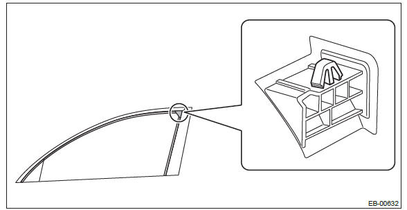
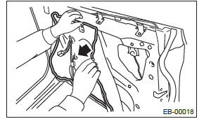
8) Detach the inner tape.
NOTE:
- If the tape is difficult to detach, warm it by a hot air drier.
Make sure to use a home use drier. Do not use an industrial use drier.
- Wipe away any trace of tape adhesive from the door sash.
2. REAR DOOR
1) Disconnect the ground cable from battery.
2) Remove the rear door trim. <Ref. to EI-61, REAR DOOR, REMOVAL, Door Trim.>
3) Remove the sealing cover.
CAUTION:
- Carefully remove the butyl tape. Excessive force will easily break the cover.
- If the sealing cover gets broken, replace it with a new part.
4) Remove the door sash and rear door glass. <Ref. to GW-34, REMOVAL, Rear Door Glass.>
5) Remove the glass run rubber.
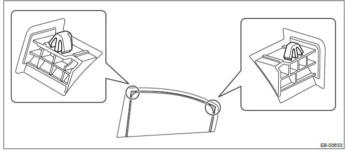
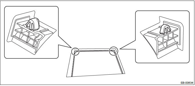
6) Release the clips, and remove the inner cover.
- Sedan model
- OUTBACK model
7) Detach the inner tape.
NOTE:
- If the tape is difficult to detach, warm it by a hot air drier.
Make sure to use a home use drier. Do not use an industrial use drier.
- Wipe away any trace of tape adhesive from the door sash.
B: INSTALLATION
CAUTION:
- Press evenly along the sash when applying the tape using a spatula or
similar object to make sure
no bubbles are formed.
If any bubbles are formed, replace the tape.
- If any wrinkles form in the tape while applying, replace the tape with new tape.
- Be sure to press the ends of the tape firmly to adhere securely. If the tape comes off at the ends or where folded, the adhesive strength is weakened and the tape may peel off.
1) Apply the inner tape along the arrow directions.
- Front
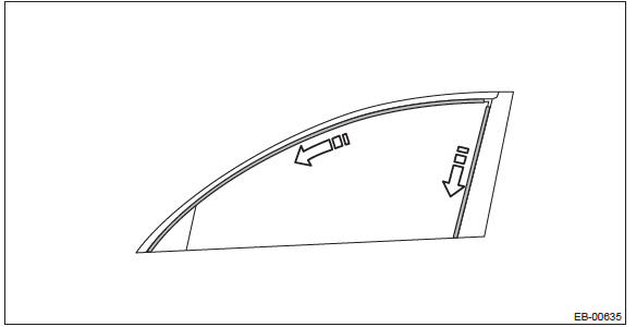
- Rear
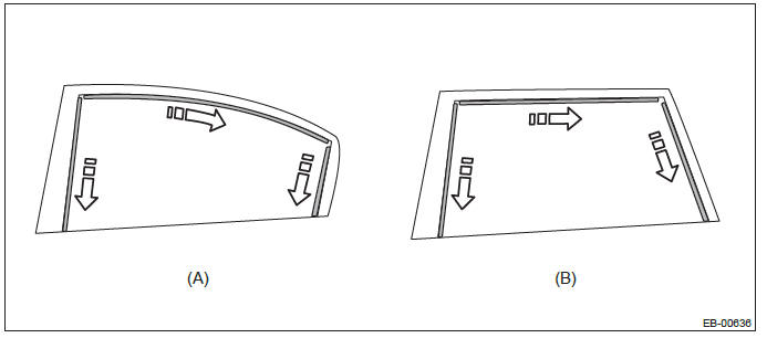
- Sedan model
- OUTBACK model
2) Install the remaining parts in the reverse order of removal.
READ NEXT:
 Trunk Lid
A: REMOVAL
1. TRUNK LID DAMPER STAY
1) Open the trunk lid.
2) Remove the trunk lid damper stay.
Float the lock pin using a flat tip screwdriver, etc. and slide it.
Remove the trunk lid damper stay
Rear Gate
A: REMOVAL
CAUTION:
Rear gate panels are heavy. When removing and installing them, always work in a
team of two or
more persons.
1. REAR GATE PANEL
1) Disconnect the ground cable from battery.
2) Re
Cruise Control System
General Description
A: COMPONENT
Engine control module (ECM)
Cruise control command switch
Stop light and brake switch
Cruise indicator light and cruise
set indicator light
Transmission contro
SEE MORE:
Difference between screen and actual road
The distance markers show the distance for a level road when the vehicle is not
loaded. It may be different from the actual distance depending on the loading conditions
or road conditions.
When there is an upward slope at the back
1) 3 feet (1 m)
The distance on the screen looks farther tha
START
CAUTION
Do not turn the ignition switch to the “START” position while the engine is running.
The engine is started in this position. The starter cranks the engine to start
it. When the key is released (after the engine has started), the key automatically
returns to the “ON” position.
