Subaru Outback (BR): General Description of Lighting System
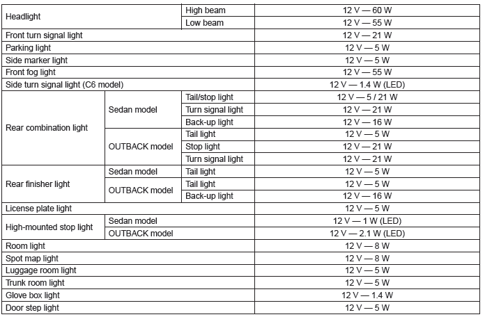
A: SPECIFICATION
B: CAUTION
- Before disassembling or reassembling parts, always disconnect the battery ground cable from battery.
When replacing the audio, control module and other parts provided with memory functions, record the memory contents before disconnecting the battery ground cable. Otherwise, the memory is cleared.
- Reassemble the parts in the reverse order of disassembly procedure unless otherwise indicated.
- Connect the connectors securely during reassembly.
- After reassembly, make sure that the functional parts operate normally.
- Yellow connectors and harnesses with yellow tapes around them are the connectors and harnesses for the airbag system. Using a tester above such circuits may cause malfunction of airbag system. Follow the cautions for the airbag system in this case. <Ref. to AB-9, CAUTION, General Description.>
- Be careful not to damage the airbag system wiring harness when servicing electrical parts and switches.
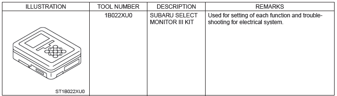
C: PREPARATION TOOL
1. SPECIAL TOOL
2. GENERAL TOOL

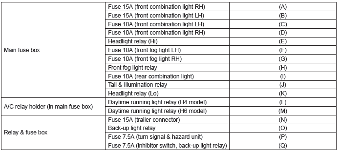
Relay and Fuse
A: LOCATION
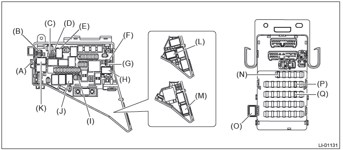
NOTE: For other related fuses, refer to the wiring diagram. <Ref. to WI-15, Power Supply Circuit.>
B: INSPECTION
1. CHECK FUSE.
1) Remove the fuse and inspect visually.
2) If the fuse is blown out, replace the fuse.
NOTE: If the fuse is blown again, check the system wiring harness.
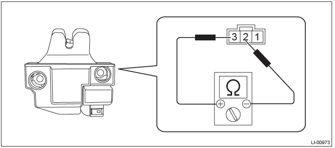
2. CHECK RELAY
1) Check the resistance between relay terminals.
2) Replace the relay if the inspection result is not within the standard value.
Headlight System
A: WIRING DIAGRAM
Refer to "Headlight System" in the wiring diagram. <Ref. to WI-172, WIRING DIAGRAM, Headlight System.>
B: INSPECTION
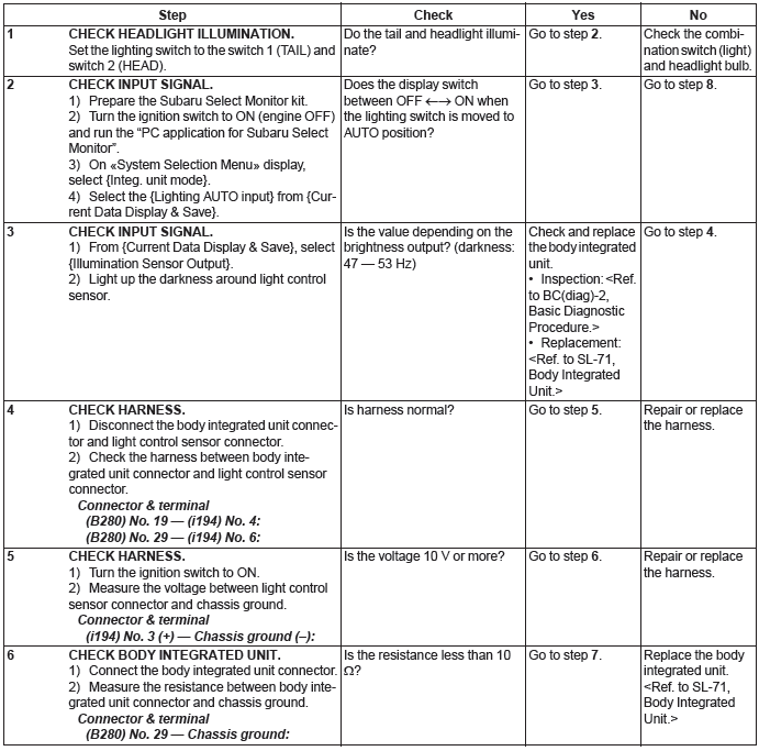
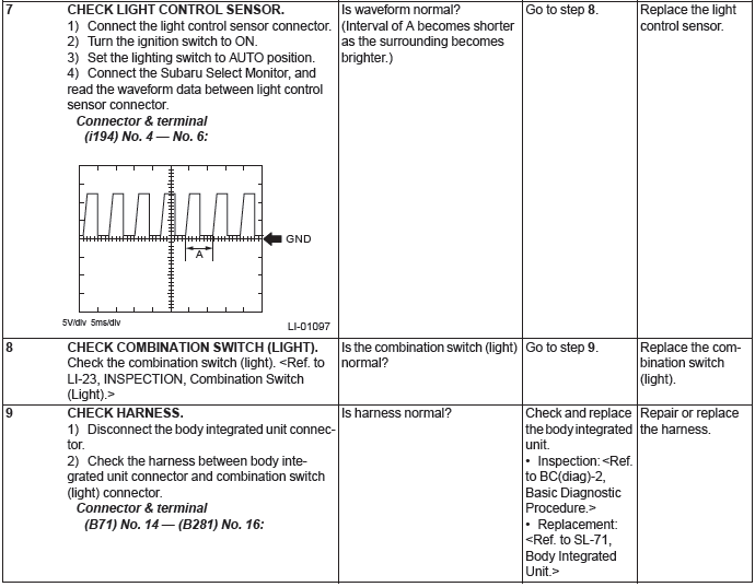
1. AUTO HEADLIGHT SYSTEM CHECK
Preparation tool:
Subaru Select Monitor III KIT
Circuit tester
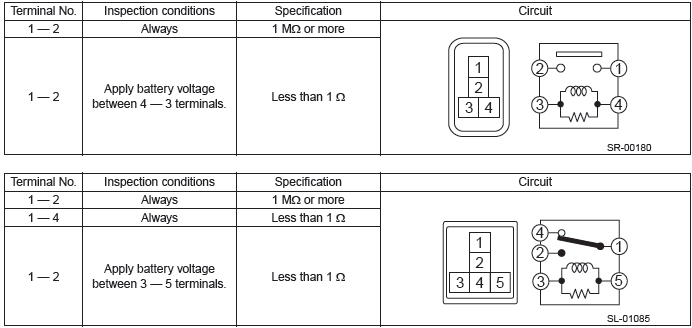
2. CHECK LIGHTING SWITCH
Measure the resistance between lighting switch terminals. <Ref. to LI-23, INSPECTION, Combination Switch (Light).>
3. CHECK DIMMER & PASSING SWITCH
Measure the resistance between dimmer & passing switch terminals. <Ref. to LI-23, INSPECTION, Combination Switch (Light).>
C: NOTE
For operation procedures of each component of the headlight system, refer to the respective section.
- Headlight Assembly: <Ref. to LI-25, Headlight Assembly.>
- Headlight bulb: <Ref. to LI-31, Headlight Bulb.>
- Combination switch (light): <Ref. to LI-19, Combination Switch (Light).>
- Light control sensor: <Ref. to LI-24, Light Control Sensor.>
Day Time Running Light System
A: WIRING DIAGRAM
Refer to "Headlight System" in the wiring diagram. <Ref. to WI-172, WIRING DIAGRAM, Headlight System.>
B: INSPECTION
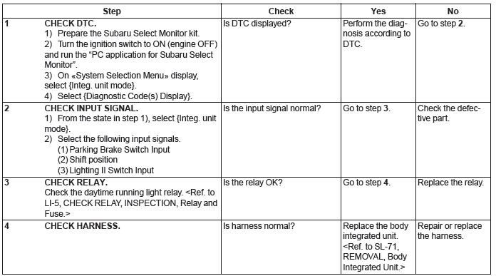
1. DAYTIME RUNNING LIGHT SYSTEM CHECK
C: NOTE
For operation procedures of each component of the daytime running light system, refer to the respective section.
- Headlight Assembly: <Ref. to LI-74, Day Time Running Resistor.>
- Headlight bulb: <Ref. to LI-31, Headlight Bulb.>
- Combination switch (light): <Ref. to LI-19, Combination Switch (Light).>
- Daytime running resistor: <Ref. to LI-74, Day Time Running Resistor.>
Clearance Light and Illumination Light System
A: WIRING DIAGRAM
Refer to "Clearance Light and Illumination Light System" in the wiring diagram. <Ref. to WI-89, WIRING DIAGRAM, Clearance Light and Illumination Light System.>
B: INSPECTION
1. CHECK LIGHTING SWITCH
Measure the resistance between lighting switch terminals. <Ref. to LI-23, INSPECTION, Combination Switch (Light).>
C: NOTE
For operation procedures of each component of the clearance light & illumination light system, refer to the respective sections.
- Combination switch (light): <Ref. to LI-19, Combination Switch (Light).>
- Clearance light/parking light bulb: <Ref. to LI-37, Clearance/Parking Light Bulb.>
- License plate light: <Ref. to LI-58, License Plate Light.>
- Ignition switch illumination: <Ref. to LI-71, Ignition Switch Illumination.>
Front Fog Light System
A: WIRING DIAGRAM
Refer to "Front Fog Light System" in the wiring diagram. <Ref. to WI-167, WIRING DIAGRAM, Front Fog Light System.>
B: INSPECTION
1. CHECK FRONT FOG LIGHT SWITCH
Measure the resistance between front fog light switch terminals. <Ref. to LI-23, INSPECTION, Combination Switch (Light).>
C: NOTE
For operation procedures of each component of the front fog light system, refer to the respective section.
- Combination switch (light): <Ref. to LI-19, Combination Switch (Light).>
- Front fog light assembly: <Ref. to LI-40, Front Fog Light Assembly.>
- Front fog light bulb: <Ref. to LI-43, Front Fog Light Bulb.>
Turn Signal Light and Hazard Light System
A: WIRING DIAGRAM
Refer to "Turn Signal Light and Hazard Light System" in the wiring diagram. <Ref. to WI-249, WIRING DIAGRAM, Turn Signal Light and Hazard Light System.>
B: INSPECTION
1. CHECK TURN SIGNAL SWITCH
Measure the resistance between turn signal switch terminals. <Ref. to LI-23, INSPECTION, Combination Switch (Light).>
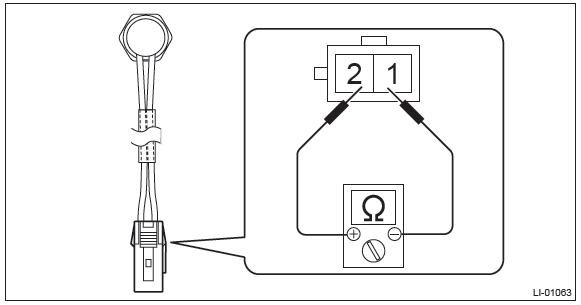
2. CHECK HAZARD SWITCH
1) Remove the A/C control panel.
- Manual A/C model: <Ref. to AC-49, MANUAL A/C MODEL, REMOVAL, Control Panel.>
- Auto A/C model: <Ref. to AC-46, AUTO A/C MODEL, REMOVAL, Control Panel.>
2) Measure the resistance between hazard switch terminals.
Preparation tool: Circuit tester
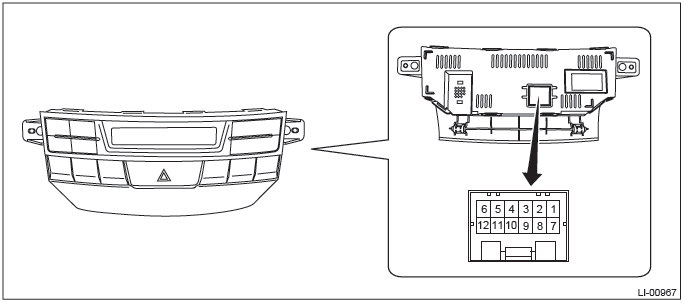
- AUTO A/C MODEL

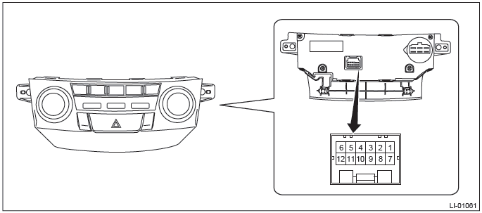
- MANUAL A/C MODEL

3) Replace the A/C control panel if the inspection result is not within the standard value.
3. CHECK TURN SIGNAL AND HAZARD MODULE
1) Measure the voltage between turn signal & hazard module connector and chassis ground.
Preparation tool: Circuit tester
Connector
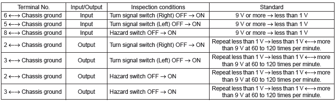
2) Replace the turn signal and hazard module if the inspection result is not within the standard value.
C: NOTE
For operation procedures of each component of the turn signal and hazard light system, refer to the respective sections.
- Combination switch (light): <Ref. to LI-19, Combination Switch (Light).>
- Front turn signal light bulb: <Ref. to LI-35, Front Turn Signal Light Bulb.>
- Side turn signal light assembly: <Ref. to LI-44, Side Turn Signal Light Assembly.>
- Rear combination light assembly: <Ref. to LI-45, Rear Combination Light Assembly.>
- Rear turn signal light bulb: <Ref. to LI-51, Rear Turn Signal Light Bulb.>
Back-up Light System
A: WIRING DIAGRAM
Refer to "Back-up Light System" in the wiring diagram. <Ref. to WI-82, WIRING DIAGRAM, Back-up Light System.>
B: INSPECTION
1. CHECK BACK-UP LIGHT SWITCH (MT MODEL)
1) Disconnect the back-up light switch connector.
2) Measure the resistance between back-up light switch terminals.
Preparation tool: Circuit tester

3) Replace the back-up light switch if the inspection result is not within the standard value.
2. CHECK INHIBITOR SWITCH (AT/CVT MODEL)
1) Disconnect the inhibitor switch connector.
2) Measure the resistance between inhibitor switch terminals.
Preparation tool: Circuit tester
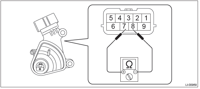

3) Replace the inhibitor switch if the inspection result is not within the standard value.
C: NOTE
For operation procedures of each component of the back-up light system, refer to the respective section.
- Rear combination light assembly: <Ref. to LI-45, Rear Combination Light Assembly.>
- Rear finisher light assembly: <Ref. to LI-54, Rear Finisher Light Assembly.>
- Back-up light bulb: <Ref. to LI-56, Back-up Light Bulb.>
Stop Light System
A: WIRING DIAGRAM
Refer to "Stop Light System" in the wiring diagram. <Ref. to WI-244, WIRING DIAGRAM, Stop Light System.>
B: INSPECTION
1. CHECK STOP LIGHT SWITCH
1) Disconnect the stop light switch connector.
2) Measure the resistance between stop light switch terminals.
Preparation tool: Circuit tester
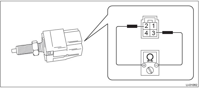

3) Replace the stop light switch if the inspection result is not within the standard value.
C: NOTE
For operation procedures of each component of the stop light system, refer to the respective section.
- Rear combination light assembly: <Ref. to LI-45, Rear Combination Light Assembly.>
- Rear finisher light assembly: <Ref. to LI-54, Rear Finisher Light Assembly.>
- Tail light/stop light bulb: <Ref. to LI-47, Tail/Stop Light Bulb.>
- High-mounted stop light: <Ref. to LI-60, High-mounted Stop Light.>
Interior Light System
A: WIRING DIAGRAM
Refer to "Interior Light System" in the wiring diagram. <Ref. to WI-177, WIRING DIAGRAM, Interior Light System.>
B: INSPECTION
1. CHECK DOOR SWITCH.
1) Remove the door switch.
2) Measure the resistance between door switch terminals.
Preparation tool: Circuit tester
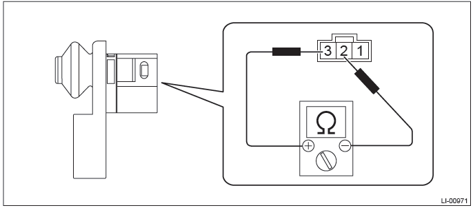

3) Replace the door switch if the inspection result is not within the standard value.
2. CHECK REAR GATE LATCH SWITCH
1) Disconnect the rear gate latch switch connector.
2) Measure the resistance between rear gate latch switch terminals.
Preparation tool: Circuit tester
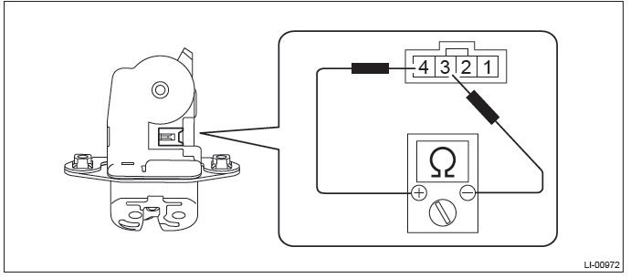

3) If the inspection result is not within the standard value, replace the rear gate latch and actuator assembly.
3. CHECK TRUNK LID LATCH SWITCH
1) Disconnect the trunk lid latch switch connector.
2) Measure the resistance between trunk lid latch switch terminals.
Preparation tool: Circuit tester

3) If the inspection result is not within the standard value, replace the trunk lid latch and actuator assembly.
C: NOTE
For operation procedures of each component of the interior light system, refer to the respective section.
- Spot map light: <Ref. to LI-62, Spot Map Light.>
- Room light: <Ref. to LI-64, Room Light.>
- Luggage room light: <Ref. to LI-66, Luggage Room Light.>
- Trunk room light: <Ref. to LI-68, Trunk Room Light.>
- Glove box light: <Ref. to LI-69, Glove Box Light.>
- Door step light: <Ref. to LI-70, Door Step Light.>
- Door switch: <Ref. to LI-76, Door Switch.>
READ NEXT:
 Combination Switch (Light)
A: REMOVAL
1) Position the front wheels straight ahead. (After moving a vehicle 5 m (16
ft) or more with front wheels positioned
straight ahead, make sure that the vehicle moves straight ahead.)
2)
Headlight Assembly
A: REMOVAL
CAUTION:
Do not perform work with wet hands.
1) Disconnect the ground cable from battery.
2) Remove the clips and remove the air intake duct. (When removing the headlight
RH)
3) Remove t
Headlight Bulb
A: REMOVAL
1. HIGH BEAM
CAUTION:
Because the halogen bulb operates at a high temperature, dirt and oil
on the bulb surface reduces
the bulb's service life. Hold the flange portion when replacing
SEE MORE:
Reverse Brake Assembly
A: REMOVAL
NOTE:
For removal of reverse brake assembly, refer to "Intermediate Case". <Ref. to
CVT-165, REMOVAL, Intermediate
Case.>
B: INSTALLATION
NOTE:
For removal of reverse brake assembly, refer to "Intermediate Case". <Ref. to
CVT-166, INSTALLATION, Intermediate
Case.>
C: DISASSE
Back-up Light Bulb
A: REMOVAL
1. SEDAN MODEL
1) Disconnect the ground cable from battery.
2) Release the lock and remove the bulb inspection cover of trunk room trim.
3) Remove the bulb socket and back-up light bulb.
2. OUTBACK MODEL
1) Disconnect the ground cable from battery.
2) Release the claws and remove the
