Subaru Outback (BR): Reverse Brake Assembly
A: REMOVAL
NOTE: For removal of reverse brake assembly, refer to "Intermediate Case". <Ref. to CVT-165, REMOVAL, Intermediate Case.>
B: INSTALLATION
NOTE: For removal of reverse brake assembly, refer to "Intermediate Case". <Ref. to CVT-166, INSTALLATION, Intermediate Case.>
C: DISASSEMBLY
1) Remove the snap ring.
2) Remove the retaining plate, drive plate, driven plate and dish plate.
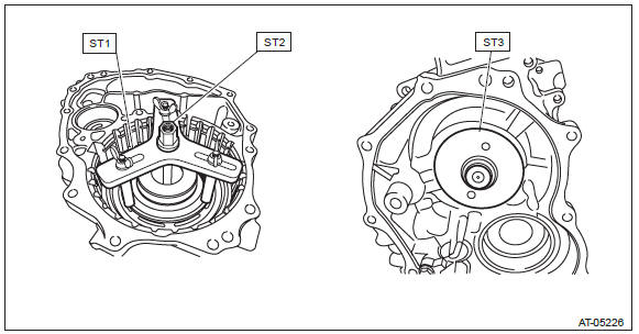
3) Set the ST1, ST2 and ST3 to intermediate case.
ST1 18762AA000 COMPRESSOR SPECIAL TOOL
ST2 18763AA000 COMPRESSOR SHAFT
ST3 18765AA000 COMPRESSOR SUPPORT
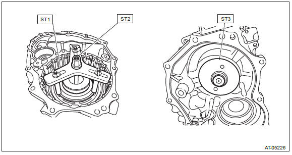
4) Compress the return spring using the set ST to remove the snap ring.
5) Using the ST, remove the snap ring and spring retainer.
- Snap ring
- Spring retainer
6) Remove the return spring.
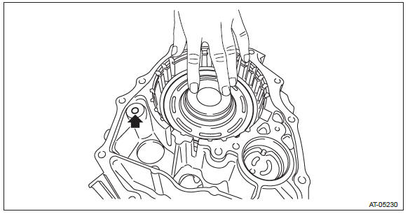
7) Remove the reverse brake piston by blowing compressed air intermittently from intermediate case hole.

D: ASSEMBLY
1) Apply CVTF to the seal of reverse brake piston and install it to intermediate case.
2) Install the return spring.
3) Install the spring retainer.
4) Set the ST1, ST2 and ST3 to intermediate case.
ST1 18762AA000 COMPRESSOR SPECIAL TOOL
ST2 18763AA000 COMPRESSOR SHAFT
ST3 18765AA000 COMPRESSOR SUPPORT
5) Compress the return spring using the set ST to install the snap ring.
6) Check the operation of reverse brake piston by blowing compressed air intermittently from intermediate case hole.
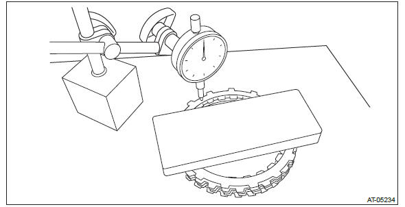
7) Place the dish plate, driven plate, drive plate and retaining plate neatly in this order on surface table.
8) Set the dial gauge to retaining plate, and read its scale.
NOTE: The value, which is read in the gauge at this time, is zero point.
9) Scale and record the weight "Z" of a flat board which will be put on retaining plate.
NOTE:
- Use a stiff board which does not bend against load as a flat board to be put on retaining plate.
- Use a flat board weighing less than 84 N (8.6 kgf, 18.9 lb).
10) Put the flat board on retaining plate.
11) Using the following formula, read the push/pull gauge and calculate "N".
N = 84 N (8.6 kgf, 18.9 lb) - Z
84 N (8.6 kgf, 18.9 lb) : Load applied to clutch plate
Z: Flat board weight
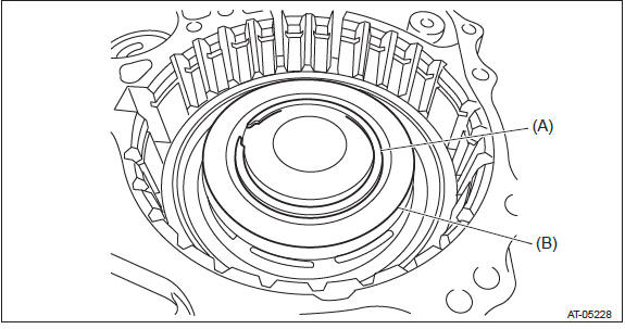
12) Press the center of retaining plate by applying a force of "N" or more using push/pull gauge, and then measure and record the compression amount "A".
NOTE: Measure at four points with a 90º interval and calculate the average.
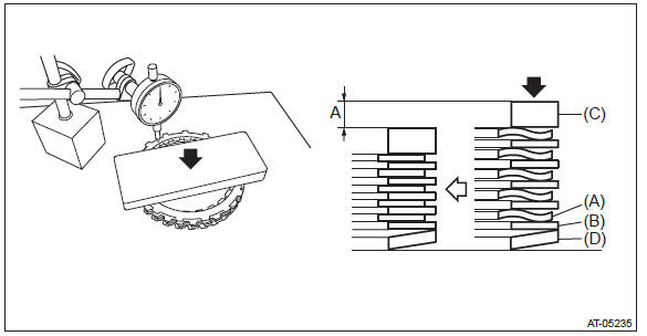
- Drive plate
- Driven plate
- Retaining plate
- Dish plate
13) Install the dish plate, drive plate, driven plate, retaining plate and snap ring to intermediate case.
NOTE: Install the dish plate in the correct direction.
14) Measure and record the clearance "B" between the retaining plate and snap ring.
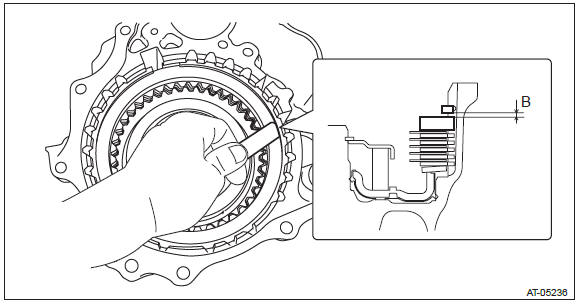
15) Piston stroke calculation Calculate with A and B dimensions recorded before. If it exceeds the limit, replace with a new drive plate and adjust within the initial standard value.
S mm (in) = A + B
S: Piston stroke
A: Compression amount of drive plate and dish plate
B: Clearance between retaining plate and snap ring
Initial standard: 2.88 - 3.18 mm (0.113 - 0.125 in)
Limit thickness: 3.38 mm (0.133 in)
E: INSPECTION
- Inspect the drive plate facing for wear and damage.
- Check the driven plate for discoloration (burnt color).
- Check for worn snap ring, fatigue or damaged return spring or deformed spring retainer.
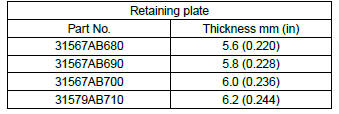
- Make sure the clearance between retaining plate and snap ring of reverse brake is within the limit. If it exceeds the limit, replace with a new drive plate and select and adjust the retaining plate within the initial standard value. <Ref. to CVT-174, ASSEMBLY, Reverse Brake Assembly.>
READ NEXT:
 Forward Clutch Assembly
A: REMOVAL
1) Remove the transmission from the vehicle. <Ref. to CVT-55, REMOVAL,
Automatic Transmission Assembly.>
2) Remove the extension case. <Ref. to CVT-138, REMOVAL, Extension Case.&
Reduction Driven Gear
A: REMOVAL
1) Remove the transmission from the vehicle. <Ref. to CVT-55, REMOVAL,
Automatic Transmission Assembly.>
2) Remove the extension case. <Ref. to CVT-138, REMOVAL, Extension Case.&
Continuously Variable Transmission Control Device
A: REMOVAL
1) Remove the transmission assembly from vehicle body. <Ref. to CVT-55, REMOVAL, Automatic Transmission Assembly.>
2) Remove the oil pan and control valve body. <Ref. to CVT-111
SEE MORE:
Continuously Variable Automatic Transmission Assembly
A: REMOVAL
1) Remove the front wheels.
2) Disconnect the ground cable from battery.
3) Remove the air intake duct. <Ref. to IN(H4SO)-9, REMOVAL, Air Intake Duct.>
4) Remove the air intake boot assembly. <Ref. to IN(H4SO)-8, REMOVAL, Air Intake Boot.>
5) Remove the ten clips and rem
2.5 L non-turbo models
1) Power steering fluid reservoir (page 11-27)
2) Manual transmission oil level gauge (MT) (page 11-23)
3) Clutch fluid reservoir (page 11-29)
4) Brake fluid reservoir (page 11-28)
5) Fuse box (page 11-46)
6) Battery (page 11-45)
7) Windshield washer tank (page 11-40)
8) Engine oil filler c
