Subaru Outback (BR): Forward Clutch Assembly
A: REMOVAL
1) Remove the transmission from the vehicle. <Ref. to CVT-55, REMOVAL, Automatic Transmission Assembly.>
2) Remove the extension case. <Ref. to CVT-138, REMOVAL, Extension Case.>
3) Remove the rear drive shaft. <Ref. to CVT-141, REMOVAL, Rear Drive Shaft.>
4) Remove the transfer clutch assembly. <Ref. to CVT-146, REMOVAL, Transfer Clutch.>
5) Remove the transfer reduction driven gear. <Ref. to CVT-158, REMOVAL, Transfer Reduction Driven Gear.>
6) Remove the intermediate case. <Ref. to CVT-165, REMOVAL, Intermediate Case.>
7) Remove the thrust needle bearing.
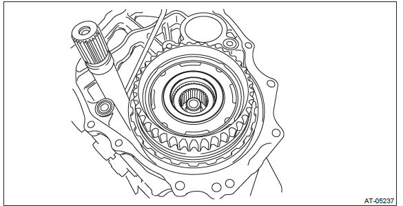
8) Remove the forward clutch assembly.
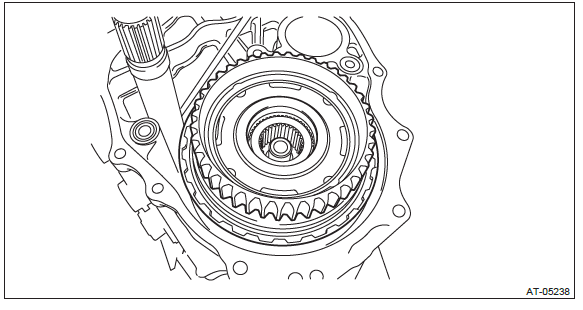
9) Remove the washer.
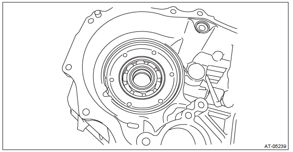
B: INSTALLATION
1) Select a washer. <Ref. to CVT-198, ADJUSTMENT, Forward Clutch Assembly.>
2) Install the selected washer.
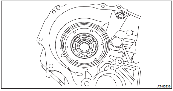
3) Install the forward clutch assembly.
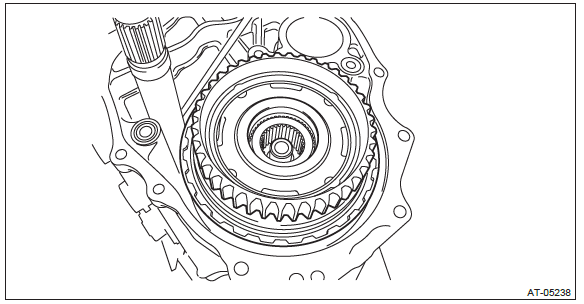
4) Install the thrust needle bearing.
NOTE: Install the thrust needle bearing in the correct direction.
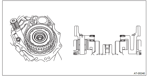
5) Install the intermediate case. <Ref. to CVT-166, INSTALLATION, Intermediate Case.>
6) Install the transfer reduction driven gear assembly. <Ref. to CVT-158, INSTALLATION, Transfer Reduction Driven Gear.>
7) Install the transfer clutch assembly. <Ref. to CVT-147, INSTALLATION, Transfer Clutch.>
8) Install the rear drive shaft. <Ref. to CVT-141, INSTALLATION, Rear Drive Shaft.>
9) Install the extension case. <Ref. to CVT-138, INSTALLATION, Extension Case.>
10) Install the transmission to vehicle. <Ref. to CVT-70, INSTALLATION, Automatic Transmission Assembly.>
C: DISASSEMBLY
1) Remove the planetary carrier assembly.
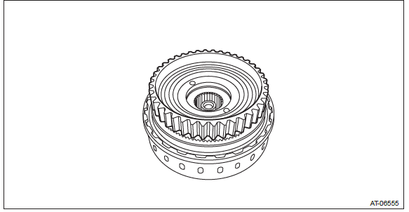
2) Remove the thrust needle bearing.
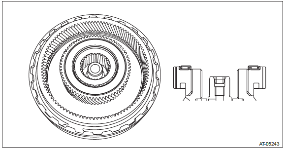
3) Remove the snap ring.
NOTE: Use marking or labeling to the upper snap ring for measurement of the snap ring thickness when selecting the retaining plate.
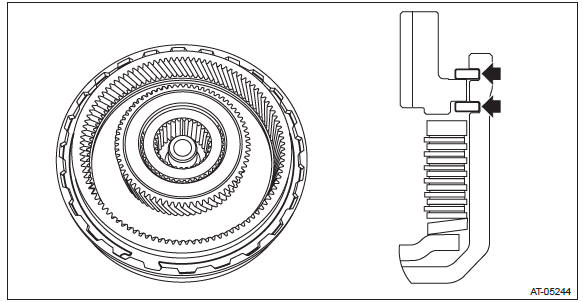
4) Remove the internal gear.
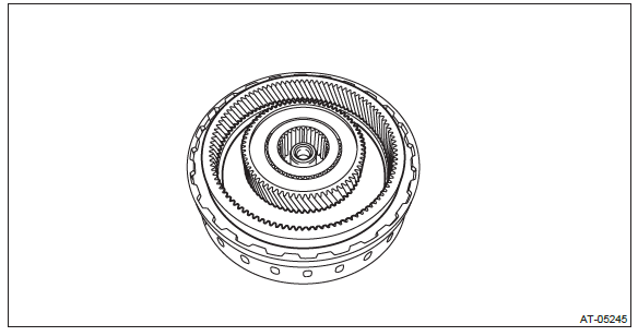
5) Remove the sun gear.
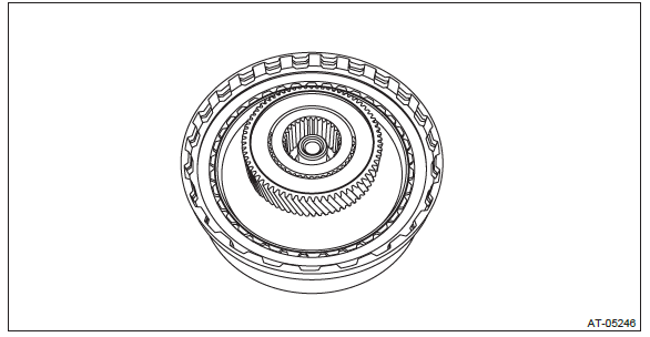
6) Remove the washer.
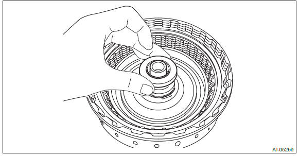
7) Remove the thrust needle bearing.
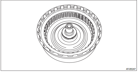
8) Remove the snap ring.
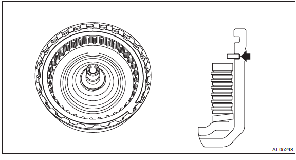
9) Remove the retaining plate, drive plate, driven plate and dish plate.
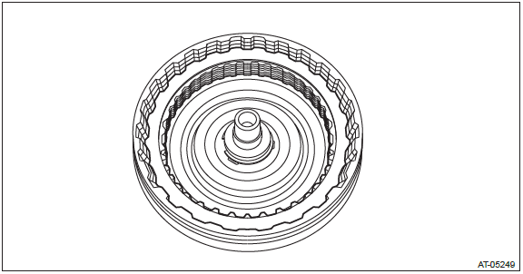
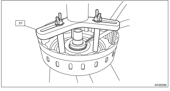
10) Using the ST, remove the snap ring.
ST 18762AA000 COMPRESSOR SPECIAL TOOL
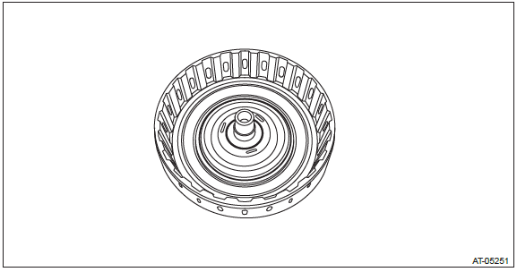
11) Remove the forward clutch piston seal.
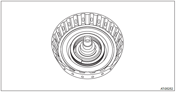
12) Remove the return spring.
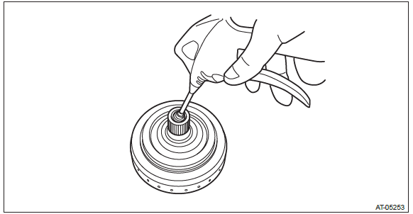
13) Remove the forward clutch piston by blowing compressed air intermittently from end of forward clutch drum.
D: ASSEMBLY
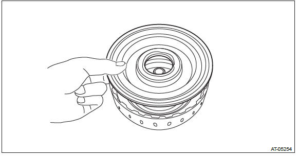
1) Install the forward clutch piston to forward clutch drum.
NOTE:
- Apply CVTF to the seal of forward clutch piston.
- Insert it all the way to the end.
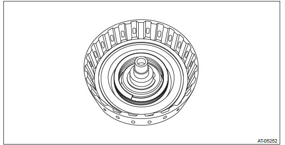
2) Install the return spring.
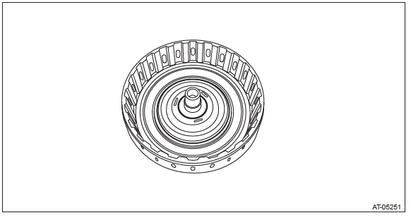
3) Install the forward clutch piston seal.
NOTE: Apply CVTF to the sealing area of forward clutch piston seal.
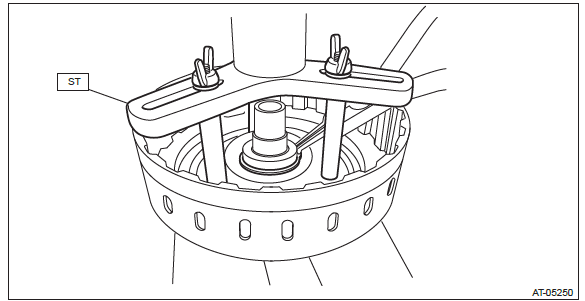
4) Compress the return spring using the ST to install the snap ring.
ST 18762AA000 COMPRESSOR SPECIAL TOOL
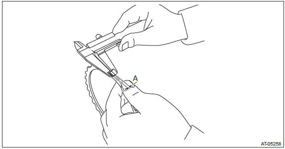
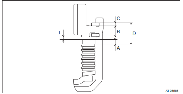
5) Measure thickness "A" of the retaining plate installed.
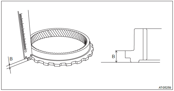
6) Measure thickness "B" of internal gear on the workbench.
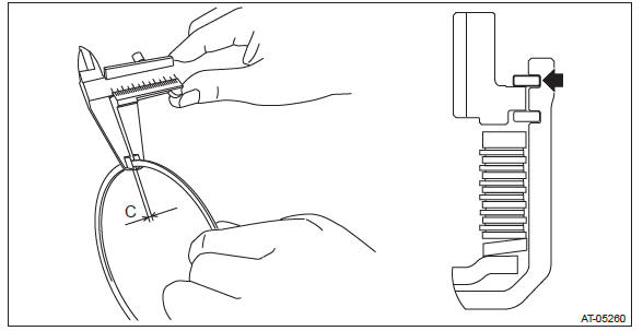
7) Measure thickness "C" of labelled or marked snap ring.
8) Install the dish plate, drive plate and driven plate.
9) Install the snap ring at the location (upper groove) indicated in the figure.
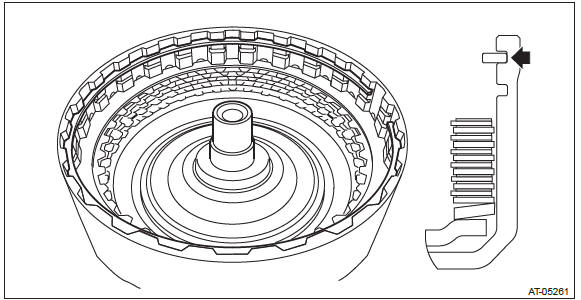
10) Measure depth "D" of snap ring and driven plate while lifting the snap ring.
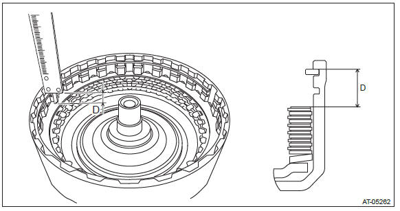
11) Calculate clearance "T" from internal gear to retaining plate with the obtained value from step 5) through step 10).
Formula: T mm (in) = D - A - B - C
12) If the value "T" obtained from step 11) exceeds the limit for use, replace the drive plate and driven plate with new parts and select the retaining plate within the initial standard value.
Initial standard: 1.2 - 1.6 mm (0.047 - 0.063 in)
Limit thickness: 2.4 mm (0.09 in)
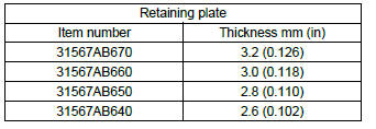
13) Remove the snap ring.
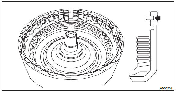
14) Replace with the selected retaining plate to install.
15) Install the snap ring to the lower groove.
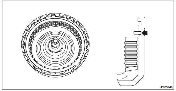
16) Install the thrust needle bearing.
NOTE: Install the thrust needle bearing in the correct direction.
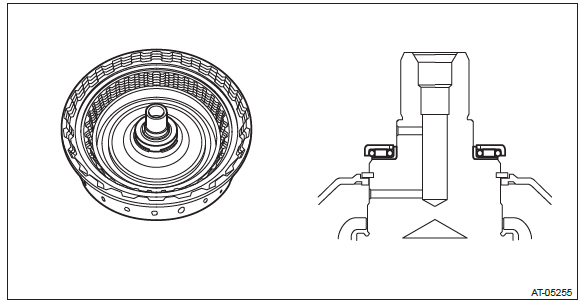
17) Install the washer.
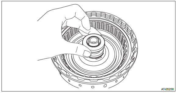
18) Install the sun gear.
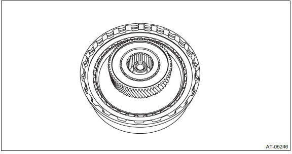
19) Install the internal gear.
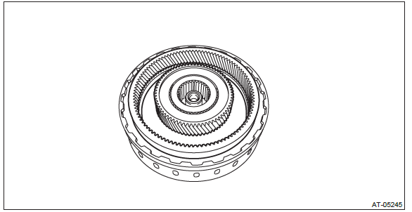
20) Install the snap ring.
21) Install the thrust needle bearing.
NOTE: Make sure to install in the right direction.
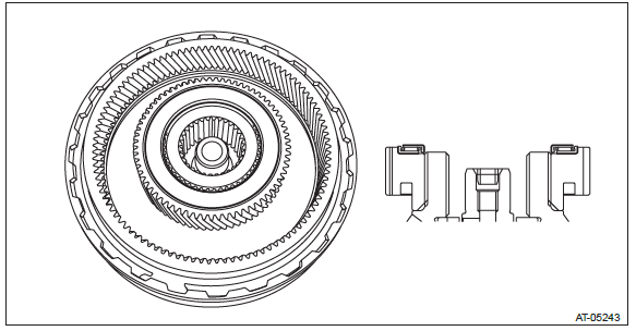
22) Install the planetary carrier assembly.
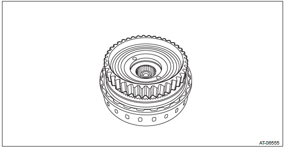
E: INSPECTION
- Check the forward clutch drum, internal gear, sun gear and forward clutch piston lip for wear or damage.
- Inspect the drive plate facing for wear and damage.
- Check the driven plate for discoloration (burnt color).
- Check for worn snap ring, fatigue or damaged return spring or deformed spring retainer.
- Make sure the clearance between retaining plate and internal gear of forward clutch is within the limit. If it exceeds the standard, replace the forward clutch assembly. <Ref. to CVT-189, ASSEMBLY, Forward Clutch Assembly.>
F: ADJUSTMENT
1) Measure depth "A" from the ST upper face to the washer catch surface.
ST 398643600 GAUGE
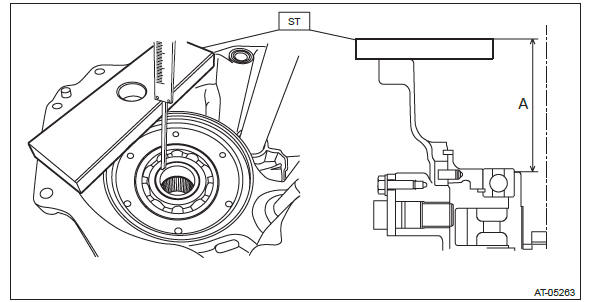
2) Install the forward clutch assembly to intermediate case.
3) Setting the ST, measure height "B" from the ST upper side to the immediate case mating surface.
ST 499575600 GAUGE
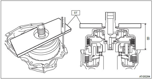
4) Obtain the thickness of washer using the following formula.
Calculation formula:
T (mm) = (A - 15) - (B - 15) - (0.35 - 0.70)
[T (in) = (A - 0.591) - (B - 0.591) - (0.014 - 0.028) ]
T: Washer thickness
A: Depth from the ST upper face to the washer catch surface
B: Height from the upper surface of the ST to the mating surface of the
intermediate case
15 mm (0.591 in): Thickness of ST
0.35 - 0.70 mm (0.014 - 0.028 in): Clearance
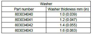
5) Select the washer matching value "T" obtained from step 4).
