Subaru Outback (BR): Reduction Driven Gear
A: REMOVAL
1) Remove the transmission from the vehicle. <Ref. to CVT-55, REMOVAL, Automatic Transmission Assembly.>
2) Remove the extension case. <Ref. to CVT-138, REMOVAL, Extension Case.>
3) Remove the rear drive shaft. <Ref. to CVT-141, REMOVAL, Rear Drive Shaft.>
4) Remove the transfer clutch assembly. <Ref. to CVT-146, REMOVAL, Transfer Clutch.>
5) Remove the transfer reduction driven gear assembly. <Ref. to CVT-158, REMOVAL, Transfer Reduction Driven Gear.>
6) Remove the intermediate case. <Ref. to CVT-165, REMOVAL, Intermediate Case.>
7) Remove the forward clutch assembly. <Ref. to CVT-180, REMOVAL, Forward Clutch Assembly.>
8) Remove the snap ring.
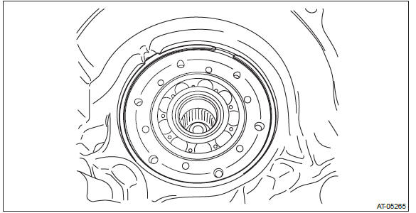
9) Remove the reduction driven gear assembly.
10) Remove the straight pin.
B: INSTALLATION
1) Install the straight pin to reduction driven gear assembly.
2) Fit the straight pin portion to the recess portion of transmission case and install the reduction driven gear and install the snap ring.
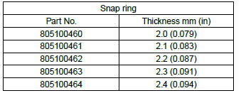
3) Select the snap ring. <Ref. to CVT-205, ADJUSTMENT, Reduction Driven Gear.>
4) Replace with the selected snap ring.
NOTE: If the clearance measured in step 3) is within standard, the snap ring replacement is not necessary.
5) Install the forward clutch assembly. <Ref. to CVT-181, INSTALLATION, Forward Clutch Assembly.>
6) Install the intermediate case. <Ref. to CVT-166, INSTALLATION, Intermediate Case.>
7) Install the transfer reduction driven gear assembly. <Ref. to CVT-158, INSTALLATION, Transfer Reduction Driven Gear.>
8) Install the transfer clutch assembly. <Ref. to CVT-147, INSTALLATION, Transfer Clutch.>
9) Install the rear drive shaft. <Ref. to CVT-141, INSTALLATION, Rear Drive Shaft.>
10) Install the extension case. <Ref. to CVT-138, INSTALLATION, Extension Case.>
11) Install the transmission to vehicle. <Ref. to CVT-70, INSTALLATION, Automatic Transmission Assembly.>
C: DISASSEMBLY
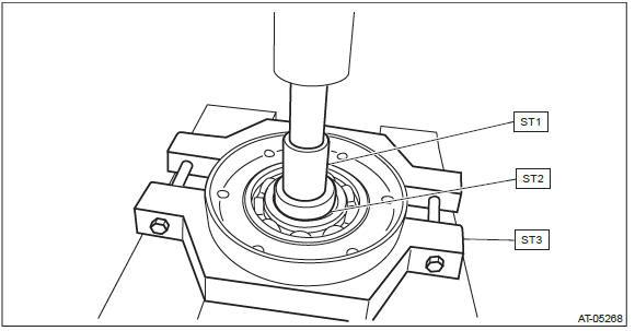
1) Remove the bearing retainer using ST1, ST2 and ST3.
ST1 899864100 REMOVER
ST2 398497701 SEAT
ST3 18767AA000 BEARING REMOVER
2) Remove the snap ring.
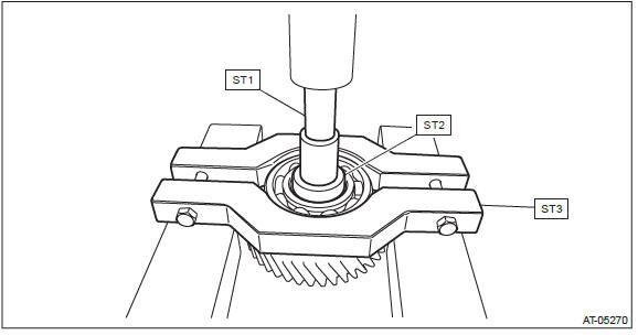
3) Remove the ball bearing using ST1, ST2 and ST3.
ST1 899864100 REMOVER
ST2 398497701 SEAT
ST3 498077600 REMOVER
D: ASSEMBLY
1) Using the ST, install the ball bearing to bearing retainer.
ST 398177700 INSTALLER
NOTE:
- Use a new ball bearing.
- Make sure to install the ball bearing in the right direction.
- Apply CVTF to the press-fitting area.
2) Using the ST, install the reduction driven gear.
ST 499277200 INSTALLER
E: INSPECTION
- Check the ball bearing for smooth rotation.
- Check the ball bearing for excessive looseness.
- Check the reduction driven gear for breakage or damage.
- Check the clearance between snap ring and transmission case and replace the snap ring as necessary.
F: ADJUSTMENT
1) Measure clearance "A" between snap ring and transmission case.
Specification: 0.05 - 0.25 mm (0.002 - 0.01 in)
2) If clearance "A" is out of standard, select the snap ring within standard.
READ NEXT:
 Continuously Variable Transmission Control Device
A: REMOVAL
1) Remove the transmission assembly from vehicle body. <Ref. to CVT-55, REMOVAL, Automatic Transmission Assembly.>
2) Remove the oil pan and control valve body. <Ref. to CVT-111
Primary Pulley and Secondary Pulley
A: REMOVAL
NOTE:
Always replace primary pulley and secondary pulley as an assembly because they
are non-disassembled
parts.
1) Remove the transmission assembly from the vehicle. <Ref. to CVT-55,
Drive Pinion Shaft Assembly in Continuously Variable Transmission
A: REMOVAL
1) Remove the transmission assembly from the vehicle. <Ref. to CVT-55, REMOVAL, Automatic Transmission Assembly.>
2) Remove the air breather hose. <Ref. to CVT-132, REMOVAL, Air
SEE MORE:
RDS text display
If the PS (Program Service Name) and/or RT (Radio Text) are available, pressing
the “TEXT” button changes the display among PS, RT and frequency. The initial setting
is “PS”.
NOTE
● The maximum number of characters that can be displayed for PS is 8.
● The maximum number
Rear Shelf Trim
A: REMOVAL
1) Disconnect the ground cable from battery and wait for at least 60 seconds
before starting work.
CAUTION:
The airbag system is fitted with a backup power supply. After disconnecting the
battery ground cable,
the airbag may operate if you do not wait for 60 seconds before starting the
