Subaru Outback (BR): General Description of Glass, Windows, Mirrors
Subaru Outback (BR) 2010-2015 Service Manual / Body / Glass/Windows/Mirrors / General Description of Glass, Windows, Mirrors
A: COMPONENT
1. FIXED GLASS (SEDAN MODEL)
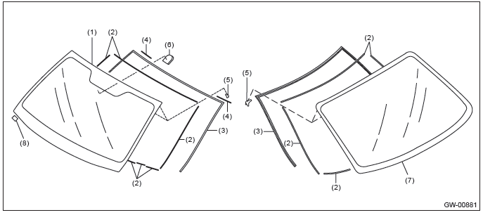
- Windshield glass
- Dam rubber
- Molding
- Seal upper side
- Locating pin
- Rearview mirror mount
- Rear window glass
- Seal A
2. FIXED GLASS (OUTBACK MODEL)
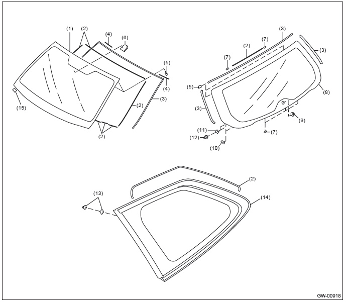
- Windshield glass
- Dam rubber
- Molding
- Seal upper side
- Locating pin
- Rearview mirror mount
- Spacer
- Rear gate glass
- Pivot
- EPT sealer
- Holder
- Clip
- Fastener
- Rear quarter glass
- Seal A
3. FRONT DOOR GLASS
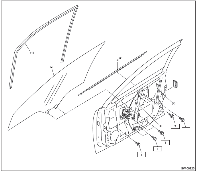
- Glass run rubber
- Front door glass
- Weather strip outer
- Door sash
- Regulator and motor ASSY
Tightening torque: N*m (kgf-m, ft-lb)
T: 7.5 (0.76, 5.5)
4. REAR DOOR GLASS
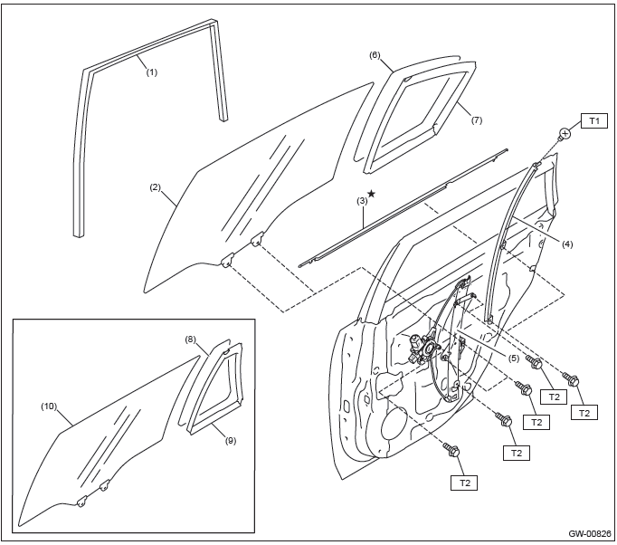
- Glass run rubber
- Rear door glass (Sedan model)
- Weather strip outer
- Door sash
- Regulator and motor ASSY
- Partition glass (Sedan model)
- Partition molding (Sedan model)
- Partition glass (OUTBACK model)
- Partition molding (OUTBACK model)
- Rear door glass (OUTBACK model)
Tightening torque: N*m (kgf-m, ft-lb)
T1: 2.2 (0.22, 1.6)
T2: 7.5 (0.76, 5.5)
5. MIRROR
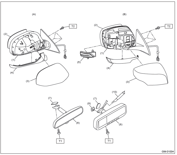
- Model without electric retractable mirror (except for C6 model)
- Model with electric retractable mirror (C6 model)
- Outer mirror
- Mirror
- Scalp cap
- Outer mirror lower cover
- Side turn signal light
- Rear view mirror
- Mount
- Rearview mirror (RCD model)
- Connector cover
- Harness cover
Tightening torque: N*m (kgf-m, ft-lb)
T1: 1.9 (0.19, 1.4)
T2: 4.5 (0.46, 3.3)
B: CAUTION
- Before disassembling or reassembling parts, always disconnect the battery ground cable from battery.
When replacing the audio, control module and other parts provided with memory functions, record the memory contents before disconnecting the battery ground cable. Otherwise, the memory is cleared.
- Avoid impact and damage to the glass.
- Reassemble the parts in the reverse order of disassembly procedure unless otherwise indicated.
- Connect the connectors securely during reassembly.
- After reassembly, make sure that the functional parts operate normally.
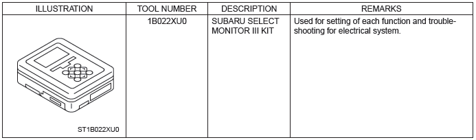
C: PREPARATION TOOL
1. SPECIAL TOOL
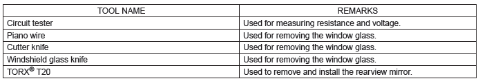
2. GENERAL TOOL
READ NEXT:
 Relay and Fuse, Power Window System
A: LOCATION
NOTE: For other related fuses, refer to the wiring diagram. <Ref. to WI-15, Power Supply Circuit.>
B: INSPECTION
1. CHECK FUSE.
1) Remove the fuse and check visually.
2) If
Front Door Glass
A: REMOVAL
1) Remove the front door trim. <Ref. to EI-60, FRONT DOOR, REMOVAL, Door
Trim.>
2) Remove the sealing cover.
CAUTION:
Carefully remove the butyl tape. Excessive force will easily
Scalp Cap
A: REPLACEMENT
1. MODEL WITHOUT ELECTRIC RETRACTABLE MIRROR
CAUTION:
When removing the mirror, be careful not to damage the back surface
of mirror with a flat tip screwdriver.
When installing the
SEE MORE:
Other sound setting controls (type A audio)
Each brief press of the “MENU” button changes the control modes in the following
sequence.
Choose the desired settings for each mode by turning the “TUNE/TRACK/CH” dial.
The control function returns to the tune/ track/channel control mode after approximately
5 seconds.
SVC setting
Air Mix Door Actuator
A: REMOVAL
1. DRIVER'S SEAT
1) Remove the instrument panel lower cover. <Ref. to EI-64, REMOVAL,
Instrument Panel Lower Cover.>
2) Remove the bolts, and remove the knee guard panel.
3) Remove the body integrated unit.
CAUTION:
Be careful to keep water and other foreign materials away from b
© 2010-2026 Copyright www.suoutback.com
